Design and Construction of Screened Wells for Agricultural Irrigation Systems
Introduction
Irrigation wells must be capable of producing adequate water during peak seasonal use and under drought conditions. Without a reliable, efficient, and economical supply of water, the entire irrigation system, regardless of the most sophisticated well head equipment design, becomes nearly useless. The well is the "heart" of irrigation systems with groundwater supplies; it must be properly designed and compatible with the pump and distribution system to ensure long life, efficiency, and economic operation.
Water well construction (Figure 1) in the state of Florida is regulated by statute and various agency rules enforced by the Florida Department of Environmental Protection (FDEP), principally through delegation to the five water management districts (WMDs).
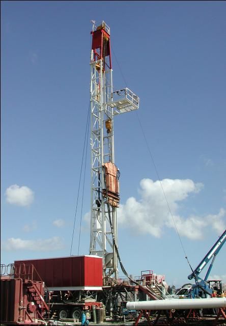
Credit: B. Boman (2003)
The potential ground water sources of irrigation water in Florida include the surficial, intermediate, and Floridan Aquifer systems. The choice of aquifer is often dictated by location. It also depends on the quantity and quality of water desired. The cavernous nature of Florida's limestone formations produces abundant quantities of water from open bore holes (generally 4-12 inches in diameter) constructed into the limestone. In some areas of Florida, especially near the coast, the depth of bore holes may be limited due to increases of salinity with depth. If well yield is too low, additional properly spaced wells may be required. Back-plugging of some irrigation wells has been successful as a remedy against upcoming deep saline waters.
The Floridan Aquifer is the primary groundwater source for agriculture throughout the state. Exceptions occur in coastal and extreme South Florida locations, where the Floridan Aquifer has poor water quality for irrigation. In these areas, surficial and intermediate (lower and upper Hawthorn) aquifers are used along with surface water. Surficial aquifer wells usually do not produce adequate quantities of water for large operations. However, they may be suitable for small systems. In areas where the Floridan Aquifer has poor water quality or is fully allocated and where the surficial and intermediate aquifers are suitable sources for agricultural irrigation use, screened wells may be required to withdraw the needed water in the most efficient manner.
A well consists of many or all of the following key parts: casing, grout, screen, open bore hole, and a well head configuration. The standards enforced by the WMDs address each of these parts with alternatives given to account for variation in geology in various areas.
The local water management district should be contacted to obtain a consumptive use permit and information on well specifications. In most cases, the district will be able to provide sufficient geologic data to help growers select the best well design with regards to water supply and construction cost. The well drilling contractor should be licensed and have experience in the construction of screened irrigation wells.
Definitions
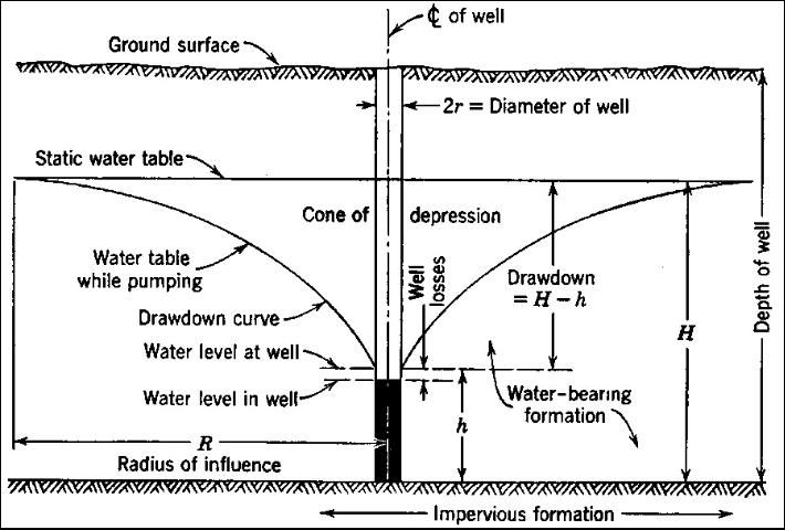
Drawdown
The depth by which the water level is lowered below the static level in a well when pumping is in progress is called drawdown. Drawdown is the difference, measured in feet of water, between the static water level and the water level during pumping. This term represents the hydraulic head, in feet of water, that is needed to cause water to flow through the aquifer toward and into the well at the rate that water is being removed from the well.
Gravel-Packed Well
Gravel-packed wells have a bore hole through the water-bearing formation that is larger in diameter than the well screen. The zone immediately surrounding the well screen is made more permeable than the aquifer by filling the space between the face of the bore hole and well screen with graded sand or gravel that is coarser than the formation.
Naturally Developed Well
A well in which the well screen is placed directly in contact with the water-bearing sand and gravel is a naturally developed well. The width of the openings in the screen is selected so that fine sand in the aquifer immediately surrounding the screen can be removed by pumping during development to create a highly permeable zone consisting of the coarser formation particles.
Specific Capacity
The yield of the well per unit of drawdown, usually expressed as gallons per minute (gpm) per foot of drawdown, is called specific capacity. It is obtained by dividing the pumping rate by the drawdown for a specific pumping period. For example, if the pumping rate is 1500 gpm and the drawdown is 20 feet, the specific capacity of the well is 75 gpm per foot of drawdown.
Well Capacity or Yield
The volume of water per unit of time discharged from a well is its capacity. Well capacity is usually measured as the pumping rate in gallons per minute (gpm) or cubic feet per second (cfs).
Static Water Level
This is the level at which water stands in a well when no water is being removed from the well either by pumping or natural flow. It is generally expressed as the distance from the ground surface (or from a measuring point near the ground surface) to the water level in the well. The level to which the water level rises in a well that taps an artesian aquifer is also referred to as the piezometric level. An imaginary surface representing the artesian pressure or hydraulic head throughout all or part of an artesian aquifer is called the piezometric surface. The piezometric surface is the real water surface, or the water table, in a water table aquifer. The artesian aquifer is different from the water table aquifer in that the saturated zone is confined by the confining layers or aquicludes.
Well Development
Well development is the process of using a variety of mechanical and chemical methods to correct damage to the formation which occurs during the drilling operation, and to remove the finer material adjacent to the screen or gravel pack. The process cleans the openings or enlarges passages in the water-bearing sand and gravel so that water can enter the well freely.
Well Efficiency
The ratio of the actual specific capacity of a well at the design yield to the maximum specific capacity possible calculated from formation hydraulic characteristics and well geometry is the well efficiency. This is the same as the ratio of the theoretical drawdown to obtain design yield from a 100% efficient well to the actual drawdown measured in the well when producing at the design yield. Efficiency is usually expressed as a percent. The difference (drawdown increase) between the theoretical drawdown and actual drawdown represents the head loss required to force water through the well screen. This head loss should be a minimum. Well efficiency should not be confused with pump efficiency. Pump efficiency is a characteristic of the pump only and is completely independent of well efficiency. For example, the pump efficiency may be 75% while the well efficiency of a poorly designed and constructed well may be only 45%.
Well Design and Construction
Preliminary Investigation
The preliminary investigation is the foundation upon which a well design depends. An examination of records from existing wells in the area should be made to determine yield, depth, and characteristics of the aquifers presently being used. Consultation should be made with the United States Geological Survey (USGS) or any other agency that may have geologic information about the area in question. Reputable local well drillers are also an important source of useful information.
If sufficient records are unavailable, test holes should be drilled to allow selection of the site with the best water production potential and to help formulate the production well design for the selected site. The information gained from test holes usually justifies the investment. In drilling test holes, samples of the aquifer should be collected so that sieve analyses and permeability tests can be made. From the completed test holes, the well designer should determine aquifer thickness, aquifer depth, and static water level of the aquifer and estimate the yield and specific capacity of a full-sized production well. A water sample should be collected and analyzed to determine the corrosion and/or incrustation characteristics of the water.
Design Procedure
After the preliminary investigation and site selection, a well design can be selected which best utilizes the hydrogeological conditions present at the site. The cased portion of the well should be designed first, and then the intake portion of the well. The cased portion of the well consists of the well casing that serves as both a housing for the pump and as a vertical conduit through which water flows upward from the intake portion of the well to the level where it enters the pump (Figure 2). The casing (or well pipe) is a very critical element in well construction. Casing may be metallic (black iron or galvanized steel) or nonmetallic (polyvinyl chloride (PVC) or ABS plastic). It must be adequately seated in a consolidated formation (limestone, sandstone, etc.) or attached to a screen suitably designed and situated in unconsolidated materials (shell, sand, gravel, etc.). The purpose of casing is to seal off materials that may enter the pumping system from strata other than the aquifer selected and prevent mixing between aquifers. To prevent contamination from surface flow into the well, the casing must be extended above surface flood water levels, and the top portion must be grouted with cement or an approved alternative material.
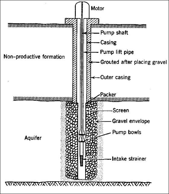
Credit: B. Boman (2003)
Casings are sealed in place with grout which protects against contamination by pollutants from the surface and acts as a seal for the casing seated into a consolidated formation. In areas where the beds of consolidated material that the casing is seated into are friable (crumble easily), the grout also helps to prevent deterioration of the casing seat (casing shoe) due to turbulence developed during pumping. Poor grouting may create problems later as pump impellers and other mechanical parts are scoured by small particles moving into the well around the casing shoe. Poor grouting may also create voids where eventual corrosion of the casing wall allows unconsolidated matter to enter the well.
The casing must be large enough to accommodate the pump. In selecting the size of the casing, the controlling factor is usually the size of pump that is required for the design yield. Table 1 shows recommended casing sizes for various ranges of well yields (pumping rate).
The well should be of sufficient diameter to allow the ascending water to move at a velocity of 5.0 feet per second or less up the well casing. Data from the preliminary investigation and chemical analyses of water samples should be reviewed to determine if the water is corrosive or encrusting. When necessary, extra heavy steel casing should be installed. In cases of severe corrosive water, stainless steel, PVC, or fiberglass casing should be used.
The capacity of individual wells is highly variable from location to location. Average estimates of expected capacities for various size wells are given in Table 1. Although Table 1 can serve as a general guideline, the specific capacity depends on the yield characteristics of the water-bearing formation and the design of the well. The overall installation must be carefully evaluated. For instance, although 1,000 gpm may be obtained from a 10-inch pump with reasonably good efficiency, the life cycle cost of a 12-inch pump installation may be less, even including the higher cost of the larger well.
Well Screen
Commercially manufactured quality well screen should be used for the wells. The well screen should have an efficient design. A well screen is considered adequate when it allows ample sand-free water to flow into the well with minimum hydraulic head loss. A properly designed well screen should have close spacing of slot openings to provide uniform open area distribution, maximum open area per foot of length, V-shaped slot openings that widen inwardly, corrosion resistance, and ample strength to resist external forces to which the screen may be subjected during and after installation. Screens with tapered slots provide hydraulic efficiency and offer self-cleaning properties. Sand grains smaller than the screen opening are easily brought into the well in the development process, while large grains are retained outside.
Screen length is an important design consideration. A screen that is too short seriously affects the efficiency of the well, whereas a well screen that is too long causes problems such as cascading water, entrained air, and accelerated corrosion and/or incrustation. The optimum length of well screen is chosen with relation to the thickness of the aquifer, available drawdown, and stratification of the aquifer.
In an artesian aquifer, the lower 70% to 80% of the thickness of the water-bearing sand should be screened, assuming the pumping level is not expected to be below the top of the aquifer. It is generally not necessary to screen the entire thickness of artesian aquifers. About 90% of the maximum specific capacity can be obtained by screening only 75% of an artesian aquifer. An exception to this rule should be made when the aquifer is highly stratified and interbedded with low permeability layers. In this case, all of the aquifer may need to be screened.
Optimum design practice dictates that the maximum available drawdown in an artesian well should be the distance from the static water level to the top of the aquifer. If it is necessary to lower the pumping level below the top of the aquifer to obtain greater yield, the screen length should be shortened and the screen should be set at the bottom of the aquifer. Attempts should be made to design and construct the well so that the pumping level stays above the top of the uppermost well screen.
For water table wells, selection of screen length is something of a compromise between two factors. While high specific capacity is obtained by using as long a screen as possible, short screens provide more available drawdown. These two conflicting aims are satisfied, in part, by using an efficient well screen. Available drawdown in a water table well is the distance between the static water level and the top of the screen. Screening the bottom 1/3 to 2/3 of the aquifer normally provides the optimum design.
Gravel Pack
Gravel-packed wells are particularly well suited to some geologic environments, but gravel packing is not a cure-all for every sand condition. Gravel pack construction is recommended:
- in aquifers consisting of fine sand,
- in loosely cemented sandstone formations,
- in extensively stratified formations consisting of alternating layers of fine and coarse sediments or thin silt and clay layers.
Gravel packing makes the zone immediately surrounding the well screen more permeable by removing the formation materials and replacing them with artificially graded coarser materials (Figure 3). The size of this artificially graded gravel should be chosen so that it retains essentially all of the formation particles. The well screen slot opening size is then selected to retain the gravel pack.
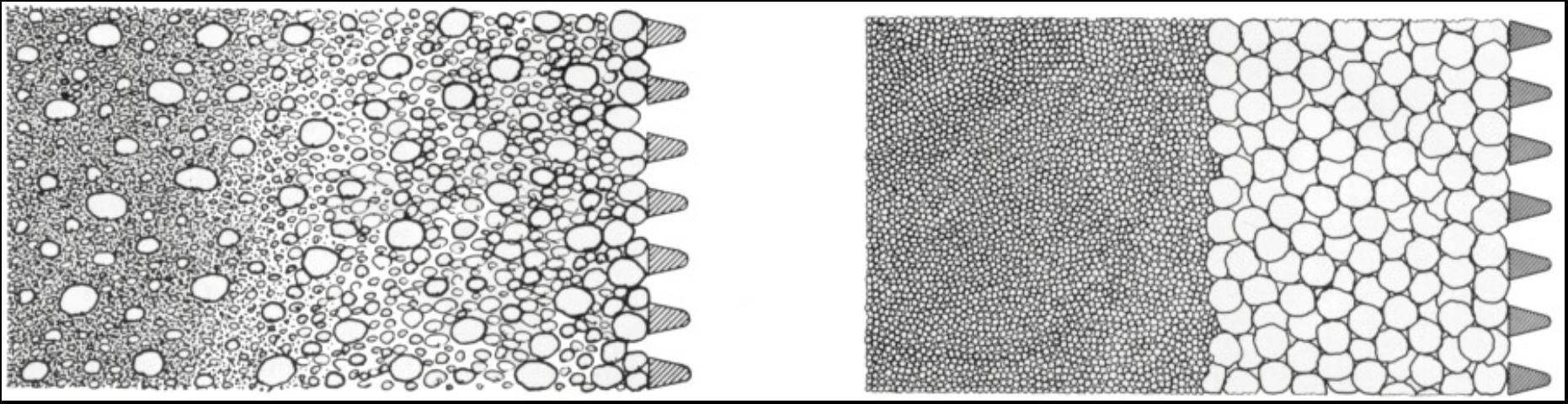
Credit: B. Boman (2003)
Gravel pack design includes specification of gradation, thickness, and quality of the gravel pack material. Part of the aquifer thickness to be screened should be evaluated by examining the samples collected during the test hole drilling. Plain casing should be set in intervals with unfavorable strata (e.g., finest sands) of the aquifer. It may be necessary to place plain (unslotted) casing between screen sections that are positioned in the best strata of the aquifer. One advantage of placing plain casing against strata composed of the finest sands and low permeability intervals is that a coarser gravel pack can be utilized. The coarser pack will allow the coarser strata of the water-bearing formation to yield maximum water. Little potential yield will be lost by setting plain casing opposite the finest sands and other low permeability strata because these layers produce little water.
A sieve analysis should be prepared for the strata comprising the portion of the aquifer where the screen will be set (Figure 4). Results of sieve analysis for the finest stratum should be used to design the gravel pack grading. It is best to design as uniform a pack as possible. A uniform gravel pack has significantly greater permeability and is easier to install without segregation. The gravel pack material should consist of clean and well-rounded grains that are smooth. These characteristics increase the permeability and porosity of the gravel pack. In addition, the particles should consist of siliceous (quartz) rather than calcareous material. The calcareous material should be limited to less than 5 percent.
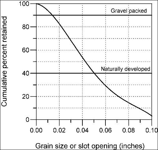
Credit: B. Boman (2003)
To ensure that an envelope of gravel will surround the entire screen, a thickness of 3 to 8 inches is recommended. This thickness will successfully retain formation particles regardless of how high the water velocity tends to carry the particles through the gravel pack. When more than 8 inches of gravel pack is provided, development of the aquifer is hampered. A thicker envelope does not significantly increase the yield of the well and does little to control sand pumping because the controlling factor is the ratio of the grain size of the pack material to the formation material. To ensure that the envelope of gravel completely surrounds the entire screen, centering guides should be used to center the screen in the borehole.
The pack material should be placed continuously, but slowly, to avoid bridging and sorting of the particles. If the screen is not centered in the bore hole and is in direct contact with the formation material (no gravel pack between the well screen and formation), sand pumping will result.
Slot Openings
The gravel pack retains the water-bearing formation, while the well screen retains the gravel pack particles. In a gravel-packed well, the size of the screen slot is selected to retain 90% or more of the gravel pack material. For the sand sieve analysis in Figure 3, the proper size screen in a gravel-packed well would have a slot opening of 0.015 inch to retain 90% of the material in the water-bearing strata.
For naturally developed wells, the size(s) of well screen slot openings will depend on the gradation of the sand, and slot openings are selected using the results of sieve analyses of water-bearing formation samples. A sieve analysis curve, such as shown in Figure 4, is plotted for each sand sample. The size of the screen opening is selected so that the screen will retain 40-50% of the sand. The remaining 50-60% of the sand particles will pass through the openings during development. If the formation is heterogeneous, it may be necessary to select various sizes of slot openings for different sections of the well screen. The use of a multiple-slot screen to custom fit the gradation of each stratum will assist in attaining the highest specific capacity possible, and will greatly reduce the possibility of pumping sand with the water.
The screen opening size that retains 40% of the particles is usually chosen when the groundwater is not particularly corrosive and when there is little doubt as to the quality of the formation samples. For example, a slot size of 0.050 inch would provide 40% retention of the materials in the water-bearing strata (Figure 4). The screen opening size that retains 50% of the sand is chosen if the water is corrosive or if the reliability of the sample is in question. If the water is corrosive, enlargement of the openings of only a few thousandths of an inch due to corrosion could cause the well to pump sand. If the water is encrusting, a size that retains 30% of particles may be selected. When this larger slot opening is selected, longer well life can be expected before plugging reduces the well yield. Large slot size also makes it possible to develop a larger area of the formation surrounding the screen. This generally increases the specific capacity of the well by increasing the well efficiency.
Screen Diameter
One important consideration that must be kept in mind when selecting the screen diameter is that the diameter can be varied without greatly affecting the well yield. Doubling the diameter of the well screen can be expected to increase the well yield by only about 10%. Screen diameter can be varied after the length of the screen and size of the screen openings have been selected. Screen diameter is selected to provide enough total area of screen openings so that the average entrance velocity of the water through the slot openings does not exceed the design standard of 0.1 feet per second (3 cm/sec). A quality well screen with maximum open area offers a decided cost advantage when different types of screening devices are compared at this entrance velocity.
The entrance velocity (V) is calculated by dividing the expected or desired yield (Y) of the well by the total area (A) of openings in the screen (V = Y/A). If the velocity is greater than 0.1 foot per second, the diameter should be increased. If the calculated entrance velocity is less than 0.1 foot per second, the screen diameter may be reduced. However, the screen diameter should not be reduced to the point that the velocity of vertical water flow to the pump exceeds 5.0 feet per second. Laboratory tests and field experience show that if the screen entrance velocity is equal to or less than 0.1 foot per second, the friction loss through the screen openings is negligible, resulting in a higher well efficiency.
Open Area
The percentage of open area of the screen should be equal to or greater than the porosity of the sand and gravel in the water-bearing formation and artificial gravel pack supported by the screen. Where the irrigation well screening device provides only 2% to 5% open area, as in perforated pipe, flow restrictions are unavoidable. This is one of the most common reasons for low efficiencies of irrigation wells. Suppose that the water-bearing sand has 30% porosity (voids) and the screening device installed has only 5% open area. With such a small open area, there will be constriction of flow. As a result, there will be additional drawdown caused by increased head loss as water moves toward and into the well.
Adequate open area should be provided by the well screen to allow the desired or design yield to enter the well at velocity of 0.1 foot per second. This hydraulic characteristic of the screen is known as transmitting capacity. If the amount of open area of a screen is known, and the recommended entrance velocity of 0.1 foot per second is used, the transmitting capacity of that screen can be readily calculated. For example, a 16-inch diameter well screen of continuous slot construction with 175 square inches (1.22 square feet) of open area per linear foot of screen can transmit 55 gpm per foot of screen body at an entrance velocity of 0.1 foot per second (Y = V × A = 0.1ft/sec × 1.22 ft2 = 0.122 ft3/sec = 54.8 gpm. This amount is generally halved to allow for blockage of the screen openings by the gravel pack to arrive at a well yield per foot of screen. Note that the transmitting capacity of a screen is a hydraulic characteristic of that screen and not a measure of the yielding capability of the water-bearing formation in which the screen is installed.
Screen Material
Depending on the results of preliminary investigation, the well screen should be fabricated of materials that are as corrosion resistant as necessary. If the screen corrodes, sand and/or gravel will enter the well, which may eventually require either replacement of screen or drilling a new well.
Corrosion of screens can occur from bimetallic corrosion if two different metals have been used in the fabrication; therefore, bimetallic screen should always be avoided. Water with high total dissolved solids accelerates this type of corrosion because the water is a more effective electrolyte. Corrosion can also occur from dissolved gases in the water such as oxygen, carbon dioxide, and hydrogen sulfide.
Well plugging by the deposits of incrustation is a common problem. Such deposits plug the screen openings and the formation and/or gravel pack immediately surrounding the well screen. When incrustation is a problem, acid treatments can be used. Therefore, corrosion-resistant material should always be used to resist the attack of strong acids introduced into the well screen during treatment.
Corrosion and incrustation can occur simultaneously in some groundwater environments. The products of corrosion can relocate themselves on the screen and form incrustations that plug the screen openings much like waters which are naturally incrusting. Removal of these deposits often requires strong acids.
The choice of the well screen material is sometimes based on strength requirements regarding column load and collapse pressure. When a long screen supports a considerable weight of pipe, it functions as a slender column. The pressure of the formation and materials caving into the well pipe can squeeze the screen. Therefore, the well material should be able to withstand the pressure. It is impossible to accurately determine or calculate earth pressures with depth but generally greater strength is needed at greater depths.
Well screens can be constructed of materials which are especially adapted to resist the corrosive attack of aggressive waters and acids. Stainless steel offers the maximum in corrosion resistance for most fresh groundwater environments and it also provides good strength. Galvanized steel is suitable for many irrigation wells where the water environment is not corrosive. It provides strength comparable to stainless steel. PVC well screens are resistant to corrosion and are often used in shallow wells. However, only limited open area can be provided and still maintain strength requirements. Therefore, nonmetallic well screens are not usually adequate for deep irrigation wells.
Well Development
Well development includes those steps in completion of a well that aim to clean, open, and enlarge passages in the formation near the bore hole so that water can enter the well more freely. Three benefits of development are to:
- correct damage or clogging of the water-bearing formation which occurred as a result of the drilling operation;
- increase the porosity and permeability of the natural formation in the vicinity of the well; and
- stabilize the sand formation around the screen or artificial gravel pack so that the well will yield sand-free water.
All of these benefits can be obtained for wells in unconsolidated aquifers if the wells are properly screened and development procedures are properly applied.
The key to successful development is to cause vigorous reversals of water flow through the screen openings that will rearrange the formation particles. Provided that adequate energy is applied to the formation, this action breaks down bridging of the gravel pack by clumps of fine particles. Better results can be obtained if development begins slowly and increases in vigor with time and when the well is pumped during the development procedure. When the development method makes simultaneous pumping impractical, the well should at least be pumped occasionally. At times, it may be wise to incorporate chemical development with the mechanical methods. This is particularly true when silt and clay are suspected of plugging of the formation.
No one particular development procedure is the best method for all geologic formations or types of well construction. Some methods are more adaptable to the particular type of drilling equipment used to construct the well, but other factors such as availability of water, air compressor, or pump may also dictate which development procedure is the most practical to use. The selection of the best method should be made on evaluation of the hydrogeologic conditions at the well site and past experience with irrigation wells in the same geologic formation. Once a method has been selected, the designer should specify the details of the procedure.
Well development methods are always needed and are generally economical regardless of the type of drilling methods used to construct the well. Proper development will improve almost any well. Surging with compressed air conveniently allows pumping from the well while development is in progress. Mechanical surging by operating a plunger in the casing, like a piston in a cylinder, is particularly adaptable when cable tool drilling equipment is used. Mechanical surging with the use of a bailer is adaptable to both cable tool and rotary drilling. Starting and stopping of a pump to produce a back lashing action is often called "rawhiding" the well. This is the simplest method of development, but it is usually the least effective since the surging effect that is created is usually not vigorous enough to obtain maximum results. High-velocity horizontal jetting with water is the most effective method of well development in most cases and is especially useful for development of gravel-packed wells.
Test Pumping
Following completion of development, the well should be test pumped. The well should be pumped for at least 12 hours at a constant pumping rate, during which time drawdown measurements are taken within the pumped well and any nearby observation wells. The primary objectives of the test pumping are to obtain information about the performance and efficiency of the well and to collect data which are used to select the permanent pumping equipment to ensure maximum pump efficiency. The information is used to evaluate the success of the design and development procedures and provides the basis to make other performance judgements and evaluations. In some cases, this information indicates that further development is necessary.
Well testing will also allow collection of data from which the hydraulic characteristics of the aquifer can be evaluated. Measurements of water table recovery at the end of a pumping test (rate at which the water table rises after pumping stops) can be beneficial in evaluating performance of irrigation wells. This data can also be used to make calculations of the aquifer hydraulic characteristics.
Drawdown
Drawdown is the distance that the water level in a well drops after pumping begins (Figure 5). Drawdown will always occur because the water in the well is not replaced instantly when it is removed by the pump. Also, drawdown creates the gradient in water levels that causes flow to the well.
Credit: B. Boman (2003)
The amount of drawdown depends on well size and efficiency, aquifer properties, and pumping. For the same well size and pumping rate, drawdown is greater in a sand or gravel aquifer as compared to the Florida limestone aquifer. Typical well drawdowns for the Floridan Aquifer are in the range of 10 to 20 feet, although drawdown can be significantly greater in specific wells. Accurate measurements of drawdown are important so that the pump can be properly positioned in a well.
Well Problems
Sand Pumping
Sand pumping causes excessive abrasion of the pump bowls and impellers, distribution pipe, emitters, and other irrigation system components. It reduces the useful life of the entire system and significantly increases maintenance costs. In addition, unnecessary costs result when sand must be periodically cleaned from the laterals, pipelines, and in some cases even from the well and pump. Sand pumping can create large underground cavities which collapse and cause land subsidence in the vicinity of the well bore. This eventually can cause total collapse of the well casing and the screen.
It is best to control sand at the well screen or gravel pack. A 2,000-gpm irrigation well operated 800 hours per year with 20 ppm sand in water will remove about 7 tons (or approximately 4.5 cubic yards) of fine sand from the water-bearing strata. In many cases, proper well design and development can prevent sand from being pumped.
In naturally developed wells, sand pumping is most often caused by using openings in the screen device that are too large to retain the finer materials of the water-bearing formation. An improper relationship between the grain size of the gravel pack material and the size of the aquifer sand grains is the major cause of sand pumping from gravel-packed wells. Often, the slot opening size in the well screens for gravel-packed wells is chosen first. A gravel pack size is then selected that will not pass through the openings in the screening device. This method gives no consideration to the size of the sand and gravel particles of the water-bearing formation. As a result, the gravel pack is often too large to properly retain the water-bearing sand, and the well pumps sand. A sieve analysis of formation samples is necessary for proper gravel pack and slot opening selection. The design procedure should proceed from the aquifer to the screening device rather than from the screening device to the formation.
In most cases, sand control cannot be achieved by merely installing a thick gravel pack. A thick gravel envelope does not significantly increase the yield of the well. Thick gravel packs don't reduce the possibility of sand pumping because the controlling factor is the ratio of the grain size of the gravel pack material to the aquifer material.
Well Inefficiency
Wells with poor efficiency result in high pumping costs due to excessive drawdown. Irrigation well efficiency should be at least 80%. Often the added operating cost in one pumping season can offset the slightly greater initial cost required for the design and construction of an efficient irrigation well (see example below). The cost resulting from inefficient operation for electric motors can be calculated by:
Cost=(Q x Hd x 0.746 x Cp)/(3960 x Ep x Em)
Where:
- Q = Pumping rate (gpm)
- Hd = Additional head required as a result of increased drawdown (feet)
- Cp = Cost per kWh (dollars)
- Ep = Pump and drive efficiency (fraction)
- Em= Motor efficiency (fraction)
Example
Assume a well with 90% efficiency when producing 2000 gpm with 20 ft drawdown. Calculate the cost savings for 90% efficient well compared to a 45% efficient well for 800 hours per year of operation. The motor efficiency is 90%, the pump efficiency is 85%, and the power cost averages 10 cents per kWh.
Specific capacity for 90% efficiency = 2000 gpm/20ft = 100 gpm/ft of drawdown
Specific capacity for 45% efficiency = 100/(90/45) = 50 gpm/ft
Drawdown for 45% efficient system to produced 2000 gpm = production/specific capacity = 2000/50 = 40 ft
Additional head required (Hd) = 40 ft - 20 ft = 20 ft
- Q = 2000 gpm
- Cp = $0.10 per kWh
- Ep = 85%
- Em= 90%
Additional cost for 45% efficient system = (2000 x 20 x 0.746 x 0.10)/(3960 x 0.85 x 0.80) = $1.10 per hour
Additional cost per year = $1.10 per hour x 800 hour = $880 per year
Many times, well inefficiency is related to the improper selection of both the gravel pack particle size and the size of slot openings in the well screen. If the ratio of the gravel pack particle size to the formation particle size is too large, it allows migration of formation particles into the gravel pack. As this migration proceeds for a period of time, successively smaller and smaller particles become lodged in the gravel pack. Eventually, its permeability is drastically reduced. As a result, the movement of water to the well is impeded.
Low efficiency is also related to skimping on construction costs with cheap, makeshift screens including various types of perforated, punched, sawed, or cut casing or pipe. These types of screens generally have limitations such as low open area percentage, poor distribution of slot openings, and slots that are inaccurate and vary in size. Usually these lower cost screens do not have openings small enough to control fine sand or retain finely graded gravel packs.
Hand-perforated or torch-slotted casing normally provides less than 3% open areas. In addition, the shape of the openings in punched or slotted pipe is such that the openings lend themselves to rapid plugging by sand particles. Slotted pipe screens typically have less than 5% of the total surface area as openings or passageways for water to enter the well. With these types of screens, the flow of water from the aquifer is restricted, since porosity of the formation is generally greater than the amount of open area provided by the well screen. Therefore, additional drawdown is required to force the water into the well, which makes the well inefficient.
A properly designed well screen allows both radial and horizontal flow to the entire well screen. Perforated pipe contains only a small number of holes, resulting in only a small percentage of the water approaching the well having direct access. As a result, there is excessive convergence of flow near the individual slot openings, which is a common cause of excessive drawdown and lower well efficiency.
Poor well development upon completion of drilling is another factor causing well inefficiency. Without proper development, wells will not achieve maximum efficiency, and this results in increased pumping costs throughout the life of the system. Although it is important to first properly design and construct the well with quality materials, it is equally as important to follow through with thorough well development.
Short Well Life
Irrigation wells should be constructed for an expected useful life of at least 25 years. The cost of drilling two or three replacement wells that would be necessary to replace the service of one properly designed and constructed well is much greater than the one-time construction cost of a good well capable of 25 years of service. In addition, maintenance costs are higher for poorly designed and poorly constructed wells.
Early failure of irrigation wells is often related to the improper selection of gravel pack and size of slot openings. Complete collapse of a well can occur due to excessive sand pumping. However, more well failures occur as a result of installing low-quality screening devices such as perforated or slotted pipe. These devices provide little open area and poor distribution of open area, which causes water to enter the well at excessively high velocities. As the velocity of water moving into a well increases, the rate of corrosion or incrustation is accelerated at the screen and within the formation or gravel pack near the bore hole. Incrustation can cause premature decrease of yield, while corrosion can cause early structural failure of the well.
Placement of the screen at elevations too near the static water level may result in premature well failure. If drawdown lowers the pumping level below the top of perforated section, water entering the well above the pumping level will free-fall (cascade) to the pumping water surface. Cascading water reduces the life of an irrigation well because it accelerates corrosion and incrustation. In addition, cascading water causes air entrainment which results in pumping of air, reduction in well yield, and erosion of pump components.
References
Driscoll, F.G. 1986. Groundwater and wells. Johnson Division, St. Paul, Minn. 1089 pp.
Frazee, J.M., Jr. 1985. Water well construction for agricultural needs. The Citrus Industry, 66: 50-59.
Haman, D.Z., A.G. Smajstrla, and G.A. Clark. 1988. Water wells for Florida irrigation systems. Circular 803. Gainesville: University of Florida Institute of Food and Agricultural Sciences. https://edis.ifas.ufl.edu/WI002 (Retrieved March 2016).
