Introduction
Cabbage production in Florida is dominated by the use of seepage or sub-irrigation. This system has traditionally been used because it is inexpensive to maintain and simple to use. Seepage irrigation works by damming tail water ditches, pumping water into open furrows and effectively raising the water table to a depth accessible to the crop root system (For more information see EDIS Publication HS1217). This type of irrigation practice is almost completely unique to Florida and is possible due to the persistence of a shallow impermeable layer in the soil profile. This system can require vast quantities of water to be pumped from the aquifer in low rainfall years. Plasticulture, or the use of drip irrigation and plastic mulch, has been proposed as an alternative production method for cabbage production in Florida.
An on-farm demonstration was setup to provide a platform for collaboration between researchers, growers and extension professionals. The demonstration was located on Greene's Farms in Bunnell, FL. The goal of the demonstration was to grow high density cabbage populations using plasticulture side by side with seepage on a commercial farm. Fertilizer and irrigation management was closely matched between systems. The plasticulture system was designed to provide a small scale installation of this technology for learning and commercial adaptation purposes. This small scale system has great potential for encouraging adoption of this type of system with low risk to the grower.
This article illustrates an innovative approach converting from seepage irrigation to plasticulture and points out some options and challenges for growers considering a plasticulture system.
Water Requirements and Pump System Upgrade
Growers using seepage irrigation require pumps that deliver high water volume without much demand for pressure. Drip and other micro-irrigation systems have varying pressure demands based on the specifications of the equipment used. Drip tape manufacturers publish minimum pressure requirements for even water distribution. It is essential that this minimum pressure be met throughout the irrigated zone for uniform distribution of not only water but fertilizer as well. These requirements are simple to achieve in commercial applications with the appropriate pump and irrigation system design.
First the amount of acreage to be drip irrigated was determined. Then the amount of water (gal/min) required from the pump was calculated. This calculation was made by summing the length of the drip tape required multiplied by the drip tape flow rate published by the manufacturer typically as gallons per minute per 100 ft of drip tape (gpm/100 ft). The length of drip tape needed is calculated as Linear Bed Feet (LBF), which is the square footage of the cropped area, divided by the bed spacing.
Comparison of typical plasticulture bed spacings, rows of plants, linear bed feet (LBF), bed width, and number of drip tapes for various crops grown in Florida. The high density population system used for this demonstration is in bold.
Example Calculation:
1 acre = 43,560 sqft » 43,560 sqft ÷ 6.67 ft bed spacing = 6,534 LBF/ acre
LBF/acre = length of plastic mulch required per acre.
This system has two drip tapes per bed therefore; the LBF/acre is doubled for length of drip tape calculation.
6,534 ft x 2 = 13,068 ft of drip tape per acre
Manufacturer specs rate the drip tape for 0.22 gpm/100 ft @ 8psi
13,068 ft ÷ 100 ft = 130.68 (100 ft sections) » 130.68 (100 ft sections) x 0.22gpm/100 ft = 28.75gpm
This example would require the pump to deliver at least 28.75 gallons of water per minute at a pressure of 8psi for each acre to be drip irrigated.
After the amount of water required from the pump has been determined, a pump can be chosen that exceeds the maximum water demand of the irrigated crop area. The type of pump used will depend on the resources available.
At this on-farm demonstration there was a pre-existing 6" well with 25hp centrifugal pump. This pump was capable of delivering much more than the required amount of water but at an insufficient pressure when all the seepage spigots from this pump were turned on (mid-season irrigation). Another major obstacle with the adaptation of seepage to drip was the fact that the pump was manually operated. In order for an irrigation system of any kind to be automated, the water supply must be "on-demand". For these reasons the existing system was adapted to meet the irrigation requirements of the plasticulture system. A solution was achieved with the cooperation of the grower and a local irrigation well/pump specialist.
The solution was to install a 2" drop pipe into the existing 6" well below the existing pump (Figure 1). The 2" drop pipe was connected to a 5hp centrifugal pump with a pressure tank and a cycle stop valve (Figure 2). A cycle stop valve is an in-line flow regulated valve located between the pump and the irrigation main line. It opens in direct relation to the amount of water the system is demanding. With a cycle stop valve, back pressure is applied to a pump and the pump still runs as it normally would but at a lower amperage. A cycle stop valve helps the pump maintain constant pressure without cycling on and off by matching the flow of water demanded by the system to the flow of water coming from the pump. The pressure tank and cycle stop valve work together to keep constant pressure on the irrigation supply line. Constant water pressure and water on demand allowed for the separation of the irrigated crop area into zones.
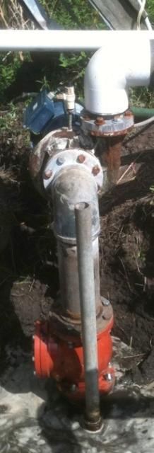
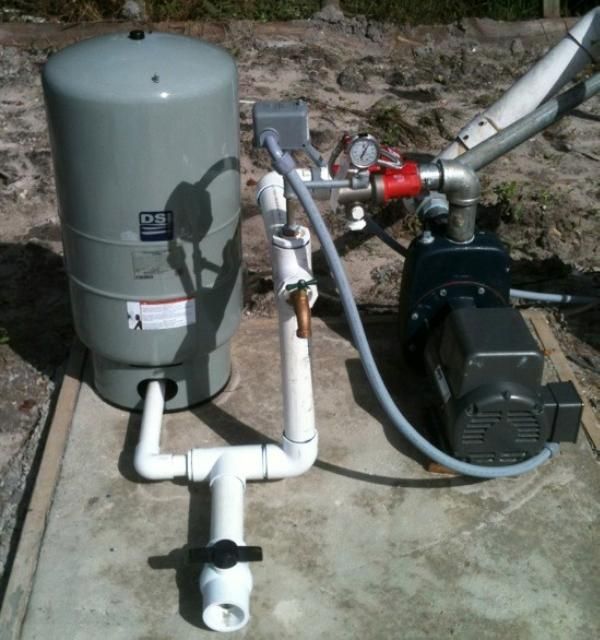
With this configuration, the existing well and pump worked as they did before with a negligible disruption in flow caused by the introduction of the 2" drop pipe. This configuration is a relatively low-cost approach for converting from seepage to drip irrigation. A major benefit of this solution is that it provides a low risk option for growers that are "on the fence" about trying drip irrigation on their farms. For a minor investment a grower can make this modification to their existing system and evaluate drip irrigation, while overcoming the learning curve associated with this upgrade in irrigation technology.
Manifold Design
The irrigation manifold was designed for long-term use and facilitation of maintenance (Figure 3). The 2" drop pipe connects the 5 hp pump to the existing 6" well as the water supply. The pump is connected to a cycle stop valve, pressure tank, and pressure switch. When the pump turns on water is drawn from the well and sent through the irrigation manifold. The manifold begins with two disk filters with pressure gauges on the input and output sides of the filters. The pressure gauges show if the disk filters are functioning properly or if they need to be cleaned. If for example, the pressure gauge on the input side of the filter reads 45 psi and the pressure gauge on the output side reads 10psi, the filter needs to be cleaned. The disk filters were arranged in a parallel design to facilitate cleaning without interrupting an irrigation event. There were two disk filters for the event that one filter must be cleaned, water can be directed through the other filter. In this way, the water supply can be maintained while maintenance is performed on the alternate filter.
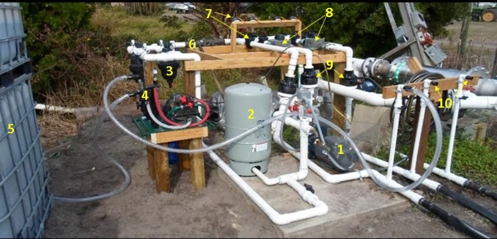
- 5-hp 2" pump with a cycle stop valve
- Pressure tank used to maintain acceptable water pressure for drip system
- Disk filter to reduce clogging of drip tape emitters
- Fertilizer/chemical injection pump
- Liquid fertilizer tank
- Brass double check valve, required for chemigation
- Timers and solenoid valves for automation of irrigation schedule
- Flow meters to measure water consumption
- 15-psi pressure regulators to reduce pressure from tank (45 psi) to allow drip tape to function properly
- Injection ports for chemigation
The next component in the manifold is the double check valve. A double check valve or back flow prevention system is mandatory on any irrigation system in which chemicals are to be injected into the water line to prevent contamination of the water supply. (For more information on back flow prevention see EDIS Circular 1403, Chemigation Equipment and Techniques for Citrus.)
The next components of the manifold are the four irrigation timers and solenoid valves that split the outgoing water into four zones. The timers chosen were battery (9v) operated and simple to use. They connect to the solenoid valves with two wires to make a circuit. Each timer was setup to schedule three to four irrigation events throughout the day to meet the crop water demand, based on crop evapotranspiration.
After the solenoid valves, flow meters were installed on two of the four zones to measure water use. Flow meters are not essential howevermonitoring water consumption is an excellent management strategy and can be useful for detecting major leaks, drip tape clogging, and other irrigation system failures. Measuring the water applied can also be combined with crop evapotranspiration data to estimate soil moisture.
Next, 15-psi pressure regulators were installed. The pressure regulators reduce the water pressure from the 30–45 psi main line to 15 psi before connecting to the poly pipe that feeds the drip tape. Excessive water pressure can break poly pipe connections, deform and split the pipe, and will cause leaks, splits, and connector failures in drip tape. Although our drip tape required a minimum of 8 psi to work properly, 15-psi regulators were used to compensate for pressure loss due to friction in the poly pipe, fittings, and drip tape.
Fertilizer injection ports were the last major component of the irrigation manifold. Quick connect fittings were installed on the injection ports and hoses that connect the injection pump to the ports for ease of injecting. It is beneficial to inject after the water pressure has been reduced because the pressure of the injected solution must be greater than the supply water pressure for the solution to enter the water line and make it out to the drip tape.
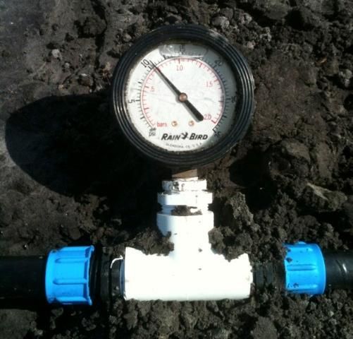
To determine if the minimum water pressure required by the drip tape to function properly was maintained, in-line pressure gauges were installed in the drip tape at the end of the irrigated zones, furthest from the pump (Figure 4). With 15 psi at the beginning of the irrigated zones, there was over 10 psi at the end of the 1,300 ft. long zones.
System Diagnostics
A properly designed drip irrigation system should be simple to maintain. Leaks and clogging are the two most common issues with drip systems. Checking for and repairing leaks in the drip tape should be a regularly scheduled task. Leaks are easy to fix with drip tape couplings and large areas can be maintained in minutes. Clogging is best treated by prevention although there are various methods that have been developed to treat clogged drip tape. For more information on prevention and general drip tape maintenance EDIS Publication HS1144.
Soil Moisture Management
Soil moisture can be more acutely managed using plasticulture compared to seepage. The plastic mulch provides a barrier, reducing soil moisture evaporation. Although row middles may appear dry, especially in low rainfall seasons, soil moisture under the plastic mulch is often much higher. Maintaining a lower water table by using drip irrigation can also aid in drainage during heavy rainfall events. Even though the irrigation requirement may be lower in wetter years, fertigation provides nutrients to the crop without driving a tractor through a field, thereby reducing the potential of spreading disease and also reducing equipment related costs.
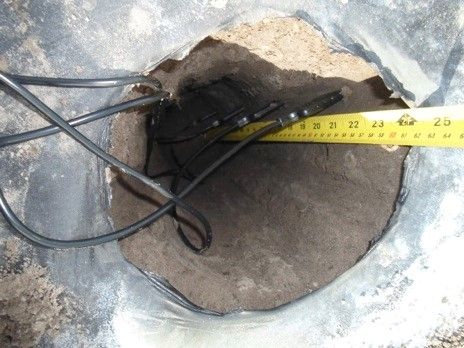
Soil moisture sensors can be very useful for understanding the daily, weekly, and monthly dynamics of soil moisture in the plant root zone. For this demonstration we installed two sensor profiles, one in seepage and one under drip. Each profile consisted of five soil moisture sensors, placed in the plant row. The sensors were installed at four depths with two at 4", and one sensor at 8", 16", and 24" (Figure 5). Two sensors were placed at the 4" depth to get an average at that depth because soil moisture at 4" can be quite variable in sandy soils. Also, in the plasticulture profile the two 4" probes were placed such that one probe was installed into an inner plant row and one into an outer plant row (Figure 6).
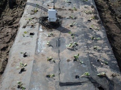
The information gathered by these sensors was saved every 15 minutes onto a drive. The drive in the plasticulture profile was connected to a cellular data network, like a cellular phone. The plasticulture data were uploaded onto the network every 6 hrs and available via the internet (Figure 7). The data provided by the sensors were used by the grower as a tool to make irrigation management decisions based on soil moisture.
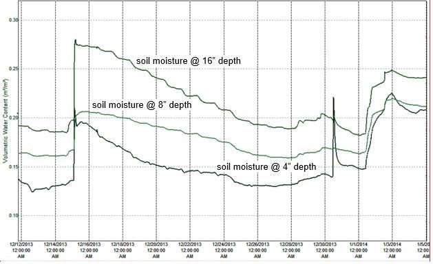
Tools like this can help growers get a better understanding of soil moisture dynamics in near real-time. Soil-moisture sensors are useful for characterizing the behavior of fields when irrigation or rainfall events occur. Soil moisture sensors can also help growers estimate the current status of the water table and when to irrigate or let water out of their ditches.
Plasticulture Management Considerations
Plasticulture has many potential benefits:
- Soil moisture retention
- Placement of water and nutrients in the crop root zone
- Weed suppression
- Reduction in water consumption
- Increased plant population for higher yield
- More efficient use of water and nutrients
With these benefits, some additional considerations must be made for a plasticulture system to be successful. This type of system demands a higher degree of management. Crew members must be trained to use and maintain the drip tape and plastic mulch. There is a potential to over irrigate and leach nutrients out of the root zone. Checking for leaks and clogs must be completed on a regular basis. There is a definite learning curve associated with converting from seepage to plasticulture and the ramifications must be understood when changing from supplying water from below to supplying water to the soil surface. Overall, plasticulture can be a simple and productive system when designed and maintained properly.
Acknowledgements
This project was supported by USDA/FDACS Specialty Crop Block Grant. We thank Mr. Tommy Miller and Greene's Farms and the cabbage growers who supported and participated in this demonstration, and the staff of the UF/IFAS Hastings Agricultural Extension Center in Hastings, FL, for their assistance with field operations and sampling.