Introduction
Soil moisture is a key factor for many agricultural processes, such as evapotranspiration, crop growth, and yield. It can be measured with either destructive (gravimetric) or nondestructive methods (soil moisture sensors) (Schmugge, Jackson, and McKim 1980). Soil moisture sensors such as time domain reflectometers (TDRs) allow for continuous, automated measurements. These sensors can be used by farmers to improve irrigation efficiency (Muñoz-Carpena and Dukes 2005), which in turn leads to reduced production cost by lowering water use. The Campbell Scientific CS616 Water Content Reflectometer, a type of TDR sensor, uses a quadratic calibration equation to acquire volumetric soil moisture (VSM). The reflectometers provide soil moisture measurements with accuracies of ± 0.025 m3m-3 for certain soil properties and VSM ranges using the manufacturer-provided calibration curves (Campbell 2006). Since the sensor's output is not only dependent on the water content, but also on the physical and chemical properties of the soil, a soil-specific calibration is required to maximize accuracy for different soil types. The sensor calibration conducted in the laboratory with well-controlled water inputs and temperature is more accurate than the on-site calibration procedure (Kinzli, Manana, and Oad 2012). In laboratory procedures, a container is packed with soil, but variations exist in the methods used to add or remove water to or from the soil (Young et al. 1997; Quinones, Ruelle, and Nemeth 2003; Regalado et al. 2003). However, implementing these methods for sandy soils is challenging due to high drainage rates and difficulties in maintaining a uniform distribution of water in the soil column.
In this publication, we describe a calibration protocol for a widely used TDR sensor, the Campbell Scientific CS616 Water Content Reflectometers specific for sandy soils, which are the most predominant soil type in Florida. The goal of this work is to provide accurate calibration coefficients for soil moisture measurements in Florida. The objectives are to (1) develop a sensor calibration protocol specific for sandy soils, (2) develop a calibration curve using the protocol, and (3) demonstrate the implementation of the calibration curve for the soil moisture measurements during the Eleventh Microwave Water and Energy Balance Experiment (MicroWEX-11) (Bongiovanni et al. 2015) conducted in the UF/IFAS Plant Science Research and Education Unit (PSREU) in Citra, FL. A comparison of VSM using the laboratory-calibrated and the manufacturer-supplied coefficients shows the impact on soil moisture estimation.
Campbell Scientific CS616 Water Content Reflectometer
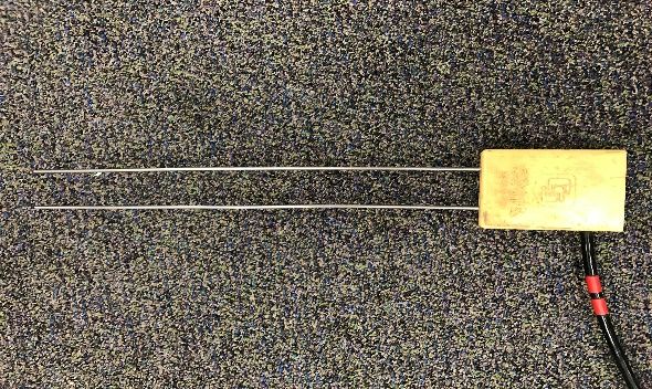
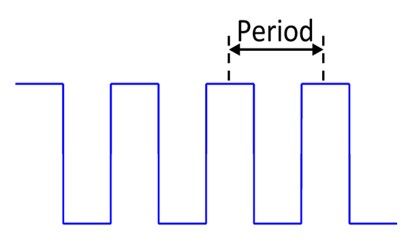
The Campbell Scientific CS616 Water Content Reflectometer has two 30 cm-long stainless steel rods that are connected to a circuit board, as shown in Figure 1. An electromagnetic pulse propagates along the rods and is reflected back when the signal reaches the end of the rods. Another pulse is then sent as soon as the reflected pulse reaches the circuit board. The number of pulses received in a given amount of time (frequency [F]) is scaled down to a frequency that is measurable using a data logger. The travel time of the signal depends on the water content and the soil medium surrounding the rods. The time required between two pulses is the output period (t=1/F), and it is the raw output of the TDR sensor, as shown in Figure 2. The output period is converted to volumetric water content using the following calibration equation,
VSM = C0 + C1 + * t + C2 * t2 (1)
where C0, C1, and C2 are calibration coefficients and t is the output period in µs. The manufacturer-specific accuracy for mineral soils (sandy loam and coarser) in the moisture range of 0.0–0.50 m3m-3 is ± 0.025 m3m-3 when the bulk electrical conductivity is less than 0.5 ds m-1 and a bulk density is less than 1.55 g cm-3. The manufacturer-specific calibration coefficients for the CS616 sensor in mineral soils are listed in Table 1.
Credit: Pang-Wei Liu, UF/IFAS
Credit: Tara Bongiovanni, UF/IFAS
Field Site
The soil samples were obtained from the upper 30 cm from the field site at the UF/IFAS Plant Science Research and Education Unit (29.41° N, 82.18° W). The soils at the site are Millhopper fine sand where the bulk density of the soil is 1.6 g cm-3 with a sand, silt, and clay percentage of 92.59%, 1.97%, and 3.94% respectively and an organic matter content of 1.5%.
Calibration Protocol
Materials
Table 2 provides a list of materials used for the sample preparation and calibration.
Credit: Pang-Wei Liu, UF/IFAS

Credit: Johanna Montanez, UF/IFAS
Soil Sample Preparation
- Place soil samples of 8,370 cm3 each into aluminum or tin baking pans and dry them in the oven at 100°C for 24 hours.
- Cool each sample and sift with the 2-mm sieve into an empty bucket.
Calibration
- The calibration is performed in an environmentally controlled room held at a constant temperature of 24°C.
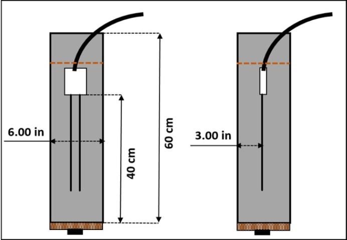
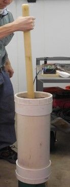
- Pour the sifted soil into a soil chamber (see Figure 3), using a disk to compact the soil every 10 cm.
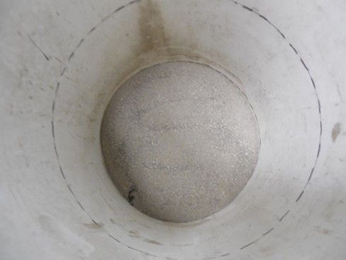
- Repeat the process until the 40 cm mark has been reached, as shown in Figures 5 and 6.
Credit: Johanna Montanez, UF/IFAS
Credit: Johanna Montanez, UF/IFAS
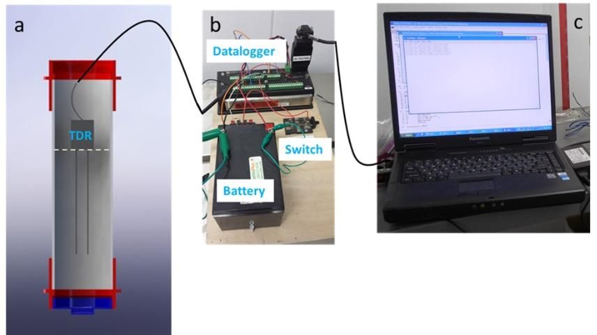
- Insert the CS616 sensor vertically into the soil until the rods are completely immersed, as shown in Figure 7(a).
- Record output periods using a data logger and a computer (see Figure 7[b] and [c]) every minute for 10 minutes for a total of 10 measurements.
Credit: Tara Bongiovanni, UF/IFAS
- After every 10-minute measurement, empty the soil into a clean bucket and add 420 mL of water. This amount equals 0.05 m3m-3 of water.
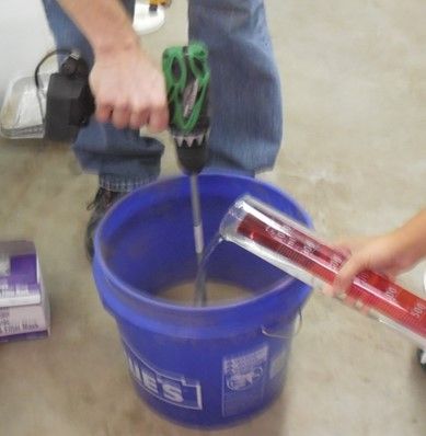
- Mix the sample thoroughly with a large drill as shown in Figure 8 and return the soil to the chamber, taking care to prevent loss of soil volume.
Credit: Johanna Montanez, UF/IFAS
- Re-insert the CS616 sensor and rerun the experiment for another 10 minutes for an additional 10 measurements at the new moisture value. After each 10-minute measurement, repeat the process until saturation is reached.
Correcting for Change in Soil Volume
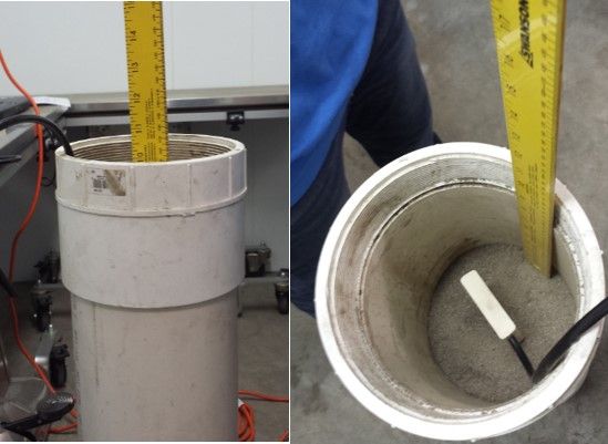
When water is added during each 10-minute experiment, the volume of soil changes compared to the original soil volume, as also observed by Kim et al. (2000). In order to account for the expansion or contraction of the soil, the actual volume of water added is determined by measuring the difference between the new and the original heights, as shown in Figure 9.
Credit: Johanna Montanez, UF/IFAS
This procedure is repeated three times for different CS616 sensors (three in this publication for a total of nine calibration trials).
Calibration Coefficients
Figure 10 shows the observed output period from the three sensors with respect to the controlled VSM compared with separate calibration curves for each sensor, the calibration curve obtained from the three sensors combined, and the manufacturer calibration curve. The observed output period from all three sensors follows a similar trend, with an inflection point around 0.10 m3m-3 that could best be modeled using a third degree polynomial (Figure 10). It was found that implementing one curve for all sensors does not significantly reduce the quality of the estimate compared to using separate curves for each sensor, as shown in Table 3. This also shows no significant bias in between the three sensors indicating the reliability of sensor samples. Applying the new calibration, the root mean square error (RMSE) with respect to the actual soil moisture was 0.011 m3m-3. Table 4 shows the new calibration coefficients in Equation 2.
VSM = C0 + C1 + * t2 + C3 * t3 (2)
Applying the standard calibration curve, the soil moisture was generally underestimated with an RMSE of 0.032 m3m-3, which is higher than the RMSE using the soil-specific calibration. Figure 11 compares the soil moisture derived from the manufacturer's standard calibration with that obtained using the new calibration. For soil moisture values below 0.022 m3m-3, soil moisture estimated with the standard calibration was higher than the soil-specific measurement, while the estimates were lower for values greater than 0.022 m3m-3. Figure 12 shows the mean and standard deviation of the curves for the separate sensors with an average regression error of 0.011 mm3m-3 for soil moisture below 0.20 m3m-3. For moisture values above 0.385 m3m-3, the errors were greater than 0.02 m3m-3, primarily due to saturation limit for this soil. Figure 13 and Table 5 compare the soil moisture estimated using the standard and the soil-specific calibrations during the MicroWEX-11 bare soil experiment (Bongiovanni et al. 2015). The soil-specific calibration is generally higher than the standard calibration.
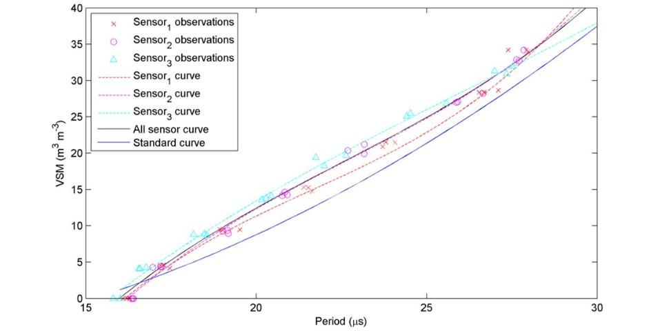
Credit: Tara Bongiovanni, UF/IFAS
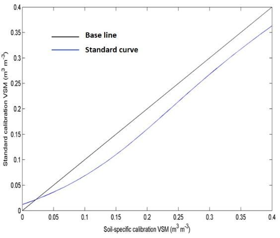
Credit: Tara Bongiovanni, UF/IFAS
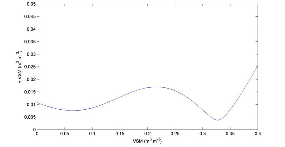
Credit: Tara Bongiovanni, UF/IFAS
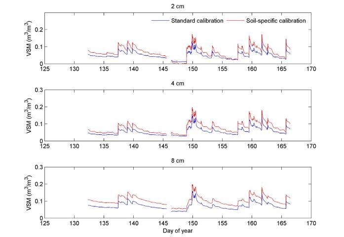
Credit: Tara Bongiovanni, UF/IFAS
The RMSEs of VSM using coefficients from the standard, separate sensor, and all sensors calibrations for the individual sensor and the three sensors combined. Credits: Tara Bongiovanni, UF/IFAS
The mean and standard deviation of soil moisture during the MicroWEX-11 bare soil experiment. Credits: Tara Bongiovanni, UF/IFAS
Summary
In this publication, we developed an in-laboratory calibration protocol for CS616 TDR sensors for sandy soils, which are typical of north central Florida. The soil-specific curve improved the RMSE by 0.02 m3m-3 compared to the standard calibration curve. The soil-specific calibration coefficients were applied to TDR measurements at the depths of 2, 4, and 8 cm during the bare soil experiment in MicroWEX-11. The difference between the soil moisture using soil-specific calibration to that using the standard calibration was up to 0.06 m3m-3, which is significant enough to affect the predictions from hydrological and meteorological models (Entekhabi et al. 2014). The overall accuracy of soil-specific calibration curves is 0.011 m3m-3. However, when the soil moisture reaches 0.385 m3m-3 and the sandy soils become saturated, the error increases to about 0.02 m3m-3.
References
Bongiovanni, T. E., H. Enos, A. Monsivais-Huertero, B. Colvin, K. Nagarajan, J. Judge, P. W. Liu, et al. 2011. Field Observations During the Eighth Microwave Water and Energy Balance Experiment (MicroWEX-8): from June 16 through August 24, 2009. AE476. Gainesville: University of Florida Institute of Food and Agricultural Sciences. https://edis.ifas.ufl.edu/ae476
Bongiovanni, T. E., P. W. Liu, K. Nagarajan, D. Preston, P. Rush, X. Duan, G. Chen, et al. 2015. Field Observations During the Tenth Microwave Water and Energy Balance Experiment (MicroWEX-10): from March 1, 2011 through January 5, 2012. AE512. Gainesville: University of Florida Institute of Food and Agricultural Sciences. https://edis.ifas.ufl.edu/ae512
Bongiovanni, T. E., P. W. Liu, K. Nagarajan, D. Preston, P. Rush, T. H. M. van Emmerik, R. Terwilleger, et al. 2015b. Field Observations During the Eleventh Microwave Water and Energy Balance Experiment (MicroWEX-11): from April 25, 2012 through December 6, 2012. AE514. Gainesville: University of Florida Institute of Food and Agricultural Sciences. https://edis.ifas.ufl.edu/ae514
Bongiovanni, T. E., P. W. Liu, K. Nagarajan, R. Terwilleger, A. Monsivais-Huertero, J. Judge, J. Fernandez-Diaz, et al. 2012. Field Observations During the Ninth Microwave Water and Energy Balance Experiment (MicroWEX-9): from March 24, 2010 through January 6, 2011. AE494. Gainesville: University of Florida Institute of Food and Agricultural Sciences. https://edis.ifas.ufl.edu/ae494
Casanova, J., T. Y. Lin, M. Y. Jang, K. J. Tien, J. Judge, O. Lanni, and L. W. Miller. 2005. Field Observations During the Fourth Microwave Water and Energy Balance Experiment (MicroWEX-4): March 10–June 14, 2005. AE362. Gainesville: University of Florida Institute of Food and Agricultural Sciences. https://edis.ifas.ufl.edu/ae362
Casanova, J., F. Yan, J. Judge, K. J. Tien, L. W. Miller, and O. Lanni. 2007. Field Observations During the Fifth Microwave Water and Energy Balance Experiment: from March 9 through May 26, 2006. AE407. Gainesville: University of Florida Institute of Food and Agricultural Sciences. https://edis.ifas.ufl.edu/ae407
Entekhabi, D., S. Yueh, P. E. O'Neill, K. H. Kellogg, A. Allen, R. Bindlish, M. Brown, et al. 2014. SMAP Handbook, Soil Moisture Active Passive: Mapping soil moisture and freeze/thaw from space. Washington, D.C.: NASA. http://smap.jpl.nasa.gov/mission/description/
Judge, J., J. Casanova, T. Y. Lin, K. J. Tien, M. Y. Jang, O. Lanni, and L. W. Miller. 2005. Field Observations During the Second Microwave Water and Energy Balance Experiment (MicroWEX-2): from March 17 through June 3, 2004. AE360. Gainesville: University of Florida Institute of Food and Agricultural Sciences. https://edis.ifas.ufl.edu/ae360
Kim, D. J., S. I. Choi, O. Ryszard, J. Feyen, and H. S. Kim. 2000. "Determination of moisture content in a deformable soil using time‐domain reflectometry (TDR)." European Journal of Soil Science 51(1): 119–127.
Kinzli, K., N. Manana, and R. Oad. 2012. "Comparison of laboratory and field calibration of a soil-moisture capacitance probe for various soils." Journal of Irrigation and Drainage Engineering ASCE 138: 310–321.
Lin, T. Y., J. Judge, K. J. Tien, M. Y. Jang, J. Casanova, O. Lanni, L. W. Miller, et al. 2005. Field Observations During the Third Microwave Water and Energy Balance Experiment (MicroWEX-3): June 16–December 21, 2004. AE361. Gainesville: University of Florida Institute of Food and Agricultural Sciences. https://edis.ifas.ufl.edu/ae361
Muñoz-Carpena, R., and M. D. Dukes. 2005. Automatic Irrigation Based on Soil Moisture for Vegetable Crops. AE354. Gainesville: University of Florida Institute of Food and Agricultural Sciences. https://edis.ifas.ufl.edu/ae354
Regalado, C. M., R. M. Carpena, A. R. Socorro, and J. H. Moreno. 2003. "Time domain reflectometry models as a tool to understand the dielectric response of volcanic soils." Geoderma 117(3): 313–330.
Schmugge, T. J., T. J. Jackson, and H. L. McKim. 1980. "Survey of methods for soil moisture determination." Water Resources Research 16(6): 961–979.
Tien, K. J., J. Judge, L. W. Miller, and O. Lanni. 2005. Field Data Report for the First Microwave Water and Energy Balance Experiment (MicroWEX-1), July 17–December 16, 2003, Citra, Florida. AE288. Gainesville: University of Florida Institute of Food and Agricultural Sciences. https://edis.ifas.ufl.edu/ae288
Quinones, H., P. Ruelle, and I. Nemeth. 2003. "Comparison of three calibration procedures for TDR soil moisture sensors." Irrigation and Drainage 52(3): 203–217.
Yan, F., H. H. Han, R. Yang, J. Casanova, J. Judge, J. M. Jacobs, O. Lanni, et al. 2007. Field Observations During the Sixth Microwave Water and Energy Balance Experiment (MicroWEX-6): from June 19 through November 30, 2006. AE409. Gainesville: University of Florida Institute of Food and Agricultural Sciences. https://edis.ifas.ufl.edu/ae409
Young, M. H., J. B. Fleming, P. J. Wierenga, and A. W. Warrick. 1997. "Rapid laboratory calibration of time domain reflectometry using upward infiltration." Soil Science Society of America Journal 61(3): 707–712.
Acknowledgments
The authors would like to acknowledge Dr. Rafael Muñoz-Carpena for his insights in developing calibration methodology.