A pond can be created by constructing a dam or embank- ment across a watercourse, by excavating a pit or dugout, or by building a dike around a natural depression area. For many farms, ponds may be the most economical way to provide water for various agricultural operations. Necessary water for irrigation, livestock or fish production, or other purposes can be stored in the pond. Ponds can also be used to store runoff from irrigation or rainfall events. The use of this surface resource could lead to reduced pumping from deep aquifer water supplies.
Ponds are excavated, embanked or, as some retention ponds in south Florida, created by building a dike around a water storage area. Frequently, ponds are created by using a combination of the above methods.
Retention ponds in South Florida are required on all new agricultural developments for runoff control, water quality control and a recharge of the shallow aquifer. In some cases, water from these ponds is also reused for irrigation or other purposes.
Since Florida’s natural topography lacks significant differ- ences in elevation, excavation is the most frequently used method for construction of deeper ponds. There are very few locations in the state where embanked ponds (created by constructing a dam) can be found. Sufficient differences in elevation for embanked ponds can be found in some northern and western parts of the state.
In Florida, the soil is often too permeable to hold water and excessive seepage losses can occur. However, in some cases the need for water can justify such a site selection. In this case some method of sealing must be used to reduce seepage losses. This publication will discuss various methods and procedures for sealing ponds.
Sealing Methods for Ponds
The selection of a sealing method depends largely on the proportions of coarse (sand and gravel) and fine materials (silts and clays) in the soil. In some cases it may be necessary to perform a laboratory test of the materials from the site to determine the particle size distribution before the sealing method is selected.
Sealing by Compaction
If the soil material at the site is well graded from small gravel or coarse sand to fine sand, silt and clay, a pond can be made relatively impervious by compaction alone. This method of sealing is the least expensive, but its use is limited to well-graded soils as described above.
Prior to compaction, the soil should be cleared of all vegetation. All holes and crevices should be filled with uniform material. The soil should be scarified to a depth of .2 to .25 m (8 to 10 inches) with a disk, roto-tiller, pulverizer or similar equipment. All debris, such as large rocks and pieces of tree roots should be removed. The loosened soil should be compacted to a dense, tight layer with four to six passes of a sheepsfoot roller. Optimum moisture conditions, which are determined during a compaction test (described below), are required for proper compaction.
The thickness of the compacted layer should not be less than .2 m (8 in) for impoundments up to 3 m (10 ft) in depth. Since seepage losses vary directly with the depth of water impounded, the thickness of the compacted layer should be increased proportionally when the depth of water exceeds 3 m (10 ft). Thus, for example, a .3 m (12 in) compacted depth will be required for a water depth of 5 m (15 ft). This will require compacting the soil in two or more layers not exceeding .2 m (8 in) each in thickness over that portion of the pond where the water depth will exceed 3 m (10 ft). To compact a layer which is more than .2 m (8 in) thick, the top layer or layers of soil will have to be removed and stockpiled while the bottom layer is being compacted.
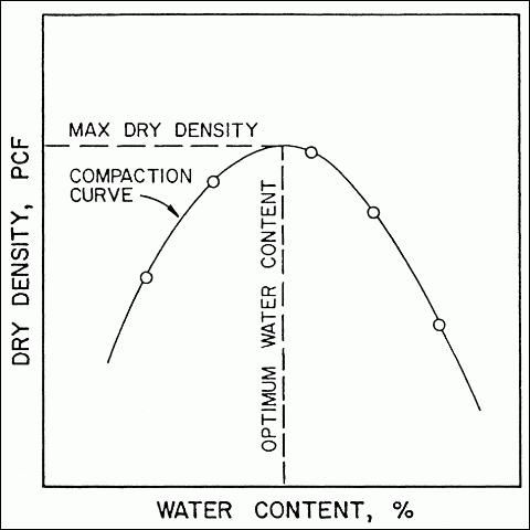
The ability to compact a soil is affected by the soil moisture content. A laboratory compaction test can be conducted to determine the optimum moisture content for compaction. This test is designed to simulate the compaction anticipated in the field. As a general rule it is recommended that the standard compaction test be used to simulate compaction for the pond bottom and embankment. In the standard compaction test, a soil at a known water content is placed in a mold and subjected to a compaction of controlled magnitude, after which the resulting bulk density of the soil is determined. The procedure is repeated at various water contents to establish the relationship between water content and bulk density of the soil.
A typical compaction curve is presented in Figure 1. The dry densities (usually in pounds per cubic foot) are plotted as ordinates (the vertical axis) and the corresponding water contents, in percentage of dry weight, as the abscissas (the horizontal axis). For most soils the curve is parabolic in shape as shown. The water content corresponding to the peak of the compaction curve is the optimum water content. At this point the compaction will result in the maximum dry density of the soil. Using a compaction curve for a given soil, it is possible to determine the optimum density and water content for soil compaction during pond construction. For best results, care should be taken to maintain the moisture level as close to the optimum value as possible during the entire compaction process.

Clay Blankets
If the soil at the site is lacking sufficient amounts of clay to prevent high seepage losses, coarsely grained sand and gravel areas can be sealed by using clay blankets. The blanket should cover the entire area over which water is to be impounded. The material for blanketing should contain approximately 20 percent clay particles by weight. The remainder of the material should consist of a wide range of particle sizes varying from small gravel to silt.
The minimum thickness of the blanket should be .3 m (12 in) for all depths of water up to 3 m (10 ft). If the water depth is greater, the thickness of the blanket should also be increased proportionally. It is recommended to increase this thickness by .05 m (2 in) for every .3 m (1 ft) of water above 3 m (10 ft). This means that a .5 m (16 in) blanket is required for a 3.6 m (12 ft) deep pond.
Clay blankets must be protected against cracking due to drying or freezing and thawing, but this is not an usual problem in Florida. A .3 m to .5 m (12 to 18 in) cover of soil or gravel will provide sufficient protection. Clay blankets should also be protected from erosion at areas where the inflow into the pond is concentrated, such as at the outflow from the recharge pump. A cantilevered pipe or a rock riprap can protect the clay blanket at these locations.
Sealing with Bentonite
Another method of pond sealing is to use bentonite. Bentonite is a fine textured colloidal clay that absorbs several times its weight in water. At complete saturation bentonite will swell 8 to 15 times its original volume. The bentonite should be spread evenly over the entire area to be sealed, well mixed with the existing material, and compacted as previously described in the procedure for sealing by compaction only. After saturation, the particles of bentonite will fill the pores in the coarse material and make it nearly impervious.
A laboratory test is recommended to determine the propor- tion of bentonite which should be used at the site. Typical applications vary from 5 to 15 kg per square meter (1 to 3 lbs per square foot), depending on site conditions. Benton- ite, like clay blankets, must also be protected against drying. Since it returns to its original volume when dry, bentonite is not recommended for sealing ponds with wide fluctuations in water levels.
Treatment with Chemical Additives
In some cases, even when the soil contains a significant amount of clay and fine materials, excessive water losses may still occur due to well developed soil structure and soil aggregation. Breakdown of the soil structure and rearrangement of clay particles can be accomplished by the application of chemical dispersing agents.
Chemical treatments are most effective in soils which have at least 50% fine materials (silt and clay) and at least 15% clay. In addition to the fine texture the soil must contain less than 0.5% (5000 ppm) soluble salts for the treatment to be effective. Chemical treatments are not effective in coarse soils. Since most of the soils in Florida are sandy, dispersing agents are not frequently used in this state for pond sealing.
The most commonly used dispersing agents are sodium polyphosphates and sodium chloride (common salt). Soda ash, technical grade, 99 to 100% sodium carbonate, can also be used. A laboratory analysis of the soil in a pond area is essential to determine which dispersing agent will be most effective and at what rate it should be applied. The dispersing agent should be spread over the entire pond area, well mixed with the existing material, and compacted at the optimum moisture content as previously described.
Flexible Membranes
In coarse textured soils flexible membranes of polyethylene, vinyl and butyl rubber can be used to prevent excessive seepage losses. Thin films of these materials are structurally weak, however, if kept intact, they are almost completely watertight. Polyethylene films are least expensive and have better aging properties than vinyl, but they are difficult to join or patch (if damaged) since repair must be performed by heat sealing. Vinyl is more resistant to impact and can be easily patched with solvent cement. Butyl rubber is structurally stronger than thin plastic membranes and it can be joined or patched with a special butyl rubber cement.
There are some flexible bentonite/fabric liners composed of sodium bentonite, a high swelling clay, and various kinds of fabrics. This type of blanket is chemically resistant and self-healing if ripped or punctured.
Semi-rigid asphalt-sealed fabric materials are also used for pond lining. The liner sheets consist of layers of asphalt mastic between asphalt-saturated felts, mats, or fabrics. When installed, lining sheets are joined with hot-mopped asphalt or a cold-applied asphalt mastic.
Membrane Standards
The minimum requirements for all membranes can be found in the American Society for Testing and Materials (ASTM) Standards or the Soil Conservation Service (SCS) Manual. The normal minimum thickness should be equal to or exceed the value presented in Table 1. The thickness is specified for the type of membrane and for the type of soil material being covered. For example, on Florida's sandy soils, a vinyl liner should be at least 8 mil thick. If you are not sure which type of material is used under certain trade names, the manufacturer should be contacted for specific recommendations.
Membrane Installation
The area to be lined should be drained and dried until the surface is firm enough to support the people and equipment to be used during the lining installation. Generally, the native soil subgrade should be disturbed as little as possible in the excavation operation to provide adequate structural bearing support. In addition, the area to be lined should be cleared of all vegetation. It is recommended to sterilize the areas to be covered with vinyl or polyethylene, since certain plants with high penetrating power can damage these thin membranes.
Membrane linings should be supplied in sections as large as can be handled by the available equipment. Field splices should use a minimum overlap of .05 m (2 in). Splices on the side slopes should be oriented perpendicular to the water surface whenever practical. This orientation reduces stress on the joint. Care should be taken not to draw taut one section over an adjoining section that is wrinkled. It is important not to stretch flexible membranes during installation. These materials should be installed in a relaxed state with a slight slack allowed in both directions.
All thin films, such as polyethylene and vinyl membranes, must be protected from mechanical damage with a cover of soil or soil and gravel. This is also required to protect these plastic materials from atmospheric weathering. The cover should be at least .15 m (6 in) thick. Butyl rubber membranes need not to be covered for protection from atmospheric weathering. However, they must be protected against mechanical damage, especially in the areas where they are likely to be damaged. For example, in livestock traffic areas all membranes should be protected with at least .22 m (18 in) of cover. If the subgrade is gravel and/or sharp pieces of rocks, a cushion layer, .02 to .05 m (1 to 2 in), of well-graded sand should be applied before the membrane is laid out. All materials used for covering the membranes should be free of large clods, sharp rocks, sticks and other objects that could damage the lining. The bottom .07 m (3 in) of the cover, which is in contact with the membrane, should be no coarser than silty sand. In general, cover material should be placed beginning at the bottom of the pond and proceeding toward the top of all slopes. Care must be taken so that the membrane will not be displaced or damaged by equipment, overburden, or sliding of cover material.
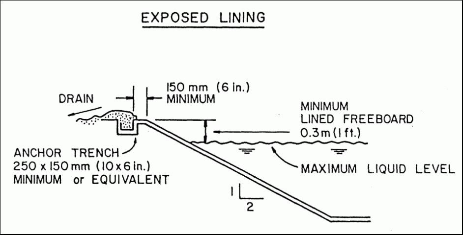
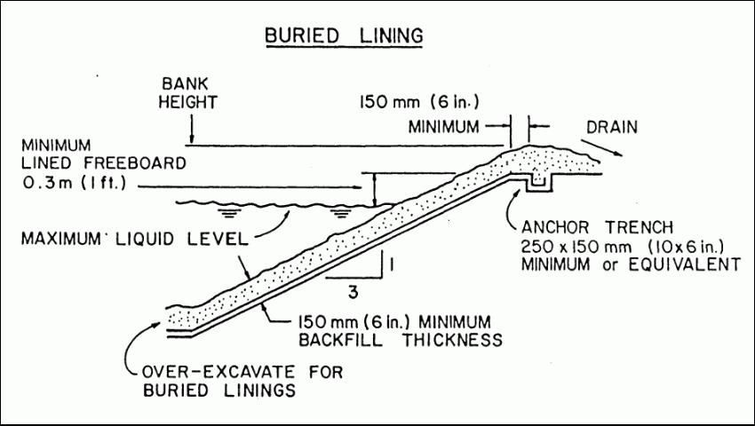
The top edges of the lining should be anchored in a trench which is at least .15 m (6 in) deep and about .25 m (10 in) wide. The trench should be excavated at the elevation of the top of the lining around the entire area to be lined. The membrane should extend across the bottom and up the far side of the trench to form a “U” shape (Figure 2 and Figure 3) The edge of the lining should be buried in the trench and secured with compacted backfill.


All banks, side slopes and fills within the area to be lined should be uniformly sloped no steeper than 3:1 for covered linings. On steeper slopes there is a danger of the cover material sliding on the membrane. For exposed rubber linings the slope can be increased to 2:1, provided this does not exceed the angle of repose for the embankment soil.
The distance between the maximum high water in the pond and the top of the embankment is called the freeboard. The lined freeboard should be at least .3 m (1 ft) above the maximum water level in ponds with surface areas of less than .4 ha (1 acre). Additional freeboard is required in larger ponds to prevent overtopping and erosion by wind-generated waves.
Summary
Water for various agricultural operations can be stored in farm ponds. Due to Florida's sandy soils, excessive seepage losses can be encountered in many ponds if a proper sealing method is not used. Various sealing methods and their applications have been described and compared in this publication.
References
ASTM Standards. 1986. Amer. Soc. for Testing and Materi- als. Philadelphia, PA.
Clark, G.A., C.D. Stanley, F.S. Zazueta, E.E. Albregts. 2020. “Farm Ponds in Florida Irrigation Systems.” Extension Bulletin 257. IFAS. University of Florida, Gainesville, FL.
Soil Conservation Service. 1984. "Ponds and Reservoirs, Chapter 11." In: Engineering Field Manual. USDA. SCS. Washington, D.C.
U.S. Army Corps of Engineer Service. 1970. "Laboratory Soils Testing." Manual EM 1110-2-1906. Dept. of the Army. Office of the Chief of Engineers. Washington, D.C.