Introduction
In Florida, in agricultural production areas with a high water table due to a shallow impermeable layer, vegetable crops have been intensively cultivated with irrigation by adjusting the water table level. This type of irrigation system is commonly called seepage irrigation or subirrigation (water table control) and relies on groundwater as the main source of irrigation water. However, the system can benefit from rainfall. The seepage system is characterized by low implementation, maintenance, and operation costs. In terms of water use efficiency, seepage systems are one of the most inefficient methods of irrigation because they require large volumes of water to raise the water table up to the crop root zone. Proper irrigation is achieved by maintaining the water table just below the crop root zone and allowing the capillarity of the soil to bring the water up into the range of the roots. A major disadvantage of these systems is the inability to wet the soil surface. Without rainfall, soil emergence of shallow seed crops can be greatly impeded. A traditional seepage system in Northeast Florida uses PVC pipes to transport water from pumps to irrigation furrows (shallow open ditches). These irrigation furrows are spaced 60 ft apart and range in length from 250 to 2,000 ft or more (Figure 1). The furrows are also used for rainfall runoff drainage. The furrows empty into an outlet ditch equipped with water retention structures (culvert pipes with boards) that are used to retain and control the water table at the appropriate water level (Figure 2).
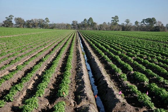
Credit: L. Zotarelli
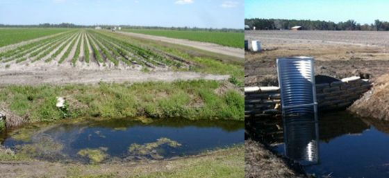
Credit: L. Zotarelli
The challenge of a seepage irrigation system is to maintain the water table just below the root zone to provide the crop with enough soil moisture to meet the evapotranspiration requirements, while at the same time avoiding root zone saturation, which may negatively impact the crop. Field evaluations of soil moisture content in the crop root zone have shown non-uniform water distribution across the field (Figure 3). The plant rows closer to the irrigation furrows tend to be wetter than the rows in the areas farther from irrigation furrows (center of the beds). Figure 3 illustrates the soil moisture distribution in the root zone of potato in a 60 ft wide x 1,200 ft long bed. Water was applied in the open furrows from the north side, and a drainage ditch was located at the south end of the field (oriented east-west). The scale of Figure 3 shows a wide range of soil moisture content, from 0% to 39% volumetric water content (VWC). Dry soil conditions, characterized in red in Figure 3, do not supply enough water to the crop. The range between 12% and 18% VWC represents soil moisture around the field soil capacity, which provides adequate moisture for crop growth. For more information about soil moisture levels, see Interpretation of Soil Moisture Content to Determine Soil Field Capacity and Avoid Over-Irrigating Sandy Soils Using Soil Moisture Sensors (https://edis.ifas.ufl.edu/ae460). Soil moisture values in the range of 18%–28% VWC, characterized in green in Figure 3, indicate wet soil conditions. Soil moisture values above 28% VWC, characterized by blue in Figure 3, indicate excessive soil water content to soil saturation, promoting anaerobic conditions that can result in reduced root and plant growth. The lack of soil moisture uniformity across the bed demonstrates the limitations of the seepage system to supply water to the crop, in that some areas of the field are overirrigated while other areas are underirrigated.
Certain irrigation management practices for seepage systems can contribute to better soil moisture uniformity. These practices include periodic laser leveling of the area and monitoring the water table during irrigation events. For more information about water table monitoring, see Simple Water Level Indicator for Seepage Irrigation (https://edis.ifas.ufl.edu/ae085).
![Figure 3 Figure 3. Map of volumetric soil moisture content (% vol/vol [e.g. ft3 of water per ft3 of soil]) at potato root zone 0–8 in. deep in a potato hill. Sampled with a time domain reflectometry (TDR) probe in a seepage irrigation system during potato season in spring of 2012 in Hastings, Florida.](/image/HS1217/12760962/5589441/5589441-2048.webp)
Credit: Libby Rens
The variability of soil moisture in the root zone can be explained by the dynamics of the water table during the processes of irrigation and drainage through the furrows.
During these processes, the water table does not rise and fall in a level line across the field; rather, it responds as shown in Figure 4. The middle of the field is slower to drain and irrigate, and water table levels rise in these areas first during rain events compared to areas closer to the irrigation furrows. The different water table levels across the field and the oscillation of the water table during the irrigation/drainage processes directly affect the soil moisture in the root zone.
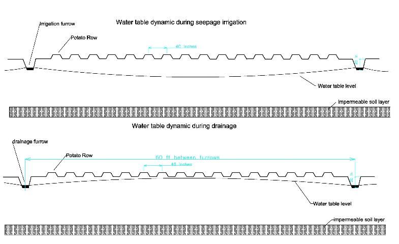
Credit: L. Zotarelli
It is important to understand that the behavior of the water table across the field during irrigation and drainage directly affects the soil moisture content in the crop root zone. This also has implications with regard to crop yield because nutrient availability, photosynthesis, and plant growth and development are dependent on proper soil moisture.
The depth of the impermeable soil layer also plays an important role in the efficiency of seepage irrigation and soil moisture distribution. For example, areas with very shallow impermeable soil layer depth (12–36 in.) would make the seepage irrigation very difficult because it would require closer (< 60 ft) in-furrow spacing, which can be impractical for a commercial operation.
To improve water table management, alternative irrigation designs can contribute to the improvement of water distribution across a field—especially in areas with shallow impermeable soil layers or in small or irregular fields—in which the conventional seepage irrigation practice is almost impossible. The subsurface drip irrigation system (SDI), which is the application of water below the soil surface by microirrigation (ASABE Standards 2001), can be considered as an alternative to improve the water distribution and time required to raise the water table for seepage irrigation. However, because the principle of the irrigation system still is subirrigation/seepage (controlling the height of the water table), this system should still be called seepage irrigation or subirrigation.
Description of the First SDI Test in Hastings
In the 1990s, UF/IFAS Research proposed the use of SDI tape with emitters to apply water directly into the plant beds in sufficiently large quantities to establish and maintain shallow water tables (Smajstrla et al. 2000). A 3-year research trial comparing the traditional seepage irrigation management with SDI showed no differences in potato yield; however, there was a consistent 36% reduction in the volume of water applied using drip compared to traditional seepage. In the proposed system, all irrigation water was applied through the buried drip system (subsurface drip) and the furrows were maintained to drain excess rainfall. Figure 5 shows the expected water table level when the irrigation water is applied through the drip. With the drip system, it is expected that the water table would be more evenly distributed across the bed compared to the water table with irrigation water being applied through the furrows (Figure 4A).

Credit: L. Zotarelli
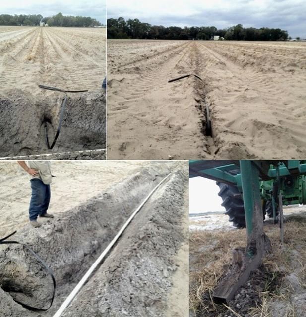
The system tested by Smajstrla et al. (2000) consisted of microirrigation tubing with 1 gph emitters spaced every 4 ft. Figure 6 shows an overview of the system tested in Hastings, Florida. Three drip tapes per bed (60 ft wide) were buried to a depth of 20 in. (Figure 6). The drip tapes were connected to a polyethylene manifold pipeline at each inlet end (Figure 7). The water was supplied from a continuously pressurized main pipeline to each manifold through an automatic solenoid valve, pressure regulator, flow meter, and vacuum breaker. The downstream end consisted of an automatic flush valve at the end of each drip tape. The operating pressure was defined according to the drip tape specifications. For this particular example, a 30 psi pressure regulator was used.
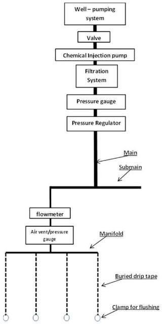
Credit: L. Zotarelli
Credit: L. Zotarelli
The system was equipped with an injection system for chemical treatment to clean the drip system. The design also included a filtration system with a Y-strainer, media filters, and screen filters.
Another important point to be considered when designing, planning, and budgeting the SDI system is energy consumption. Because SDI operates on higher pressure, energy consumption is 70% greater than seepage, despite smaller water applications with drip irrigation. The subsurface drip emitters were operated at 25 psi, which required a manifold pressure of 30 psi. The seepage system required a manifold pressure of only 5 psi.
Points to Consider before Adopting SDI for Seepage Irrigation Management
Little information is available about the design, installation, and operation of SDI for water table control in Florida. However, there are several similarities in terms of maintenance and operation between SDI and conventional drip irrigation. The similarities and challenges are discussed in this section.
1. Design and Installation
The design of an SDI system for water table management is very similar to that of a conventional drip irrigation system, except that the drip irrigation tapes should have high flow and are generally buried 6 in. below the soil (measuring between raised rows). Even though the SDI industry has grown significantly in the United States in the last decade, little research has been conducted and few professionals have provided design, installation, and guidelines for operating SDI for water table management. In several instances, the grower is responsible for system design and installation. Although few references have been published about the best depth of placement of the drip tape for subsurface irrigation, installing the drip tape above the impermeable soil layer is important. Where possible, positioning the tape below the level of cultivation helps prolong the longevity of the system. Therefore, a field survey is required to determine the average depth of the impermeable layer before determining the drip installation depth.
2. Drip Tape Specification and Number of Drip Tapes Required Per Area
The number of drip tape lines required for SDI to manage the water table is still not defined. Only one reference exists for Florida (Smajstrla et al. 2000) in which the authors successfully tested three drip lines installed per bed with 16 potato rows (40-in. in-row spacing). In this system, the operating pressure was set at the inlet of each bed at 30 psi, which resulted in an application equivalent to 0.45 in. per day. The drainage furrows were maintained (spaced 60 ft), but more research is required to evaluate the possibility of wider furrow spacing, which will result in greater available land for planting. For shallow impermeable soil layers, short distances between furrows are not recommended.
Several factors should be considered for drip tape selection, including wall thickness, emitter spacing and flow, and operational pressure. Drip tape wall thickness can range from 4 to15 mil. Thinner drip walls (4–6 mil) are recommended for surface drip systems for short-season crops; intermediate drip walls (6–10 mil) are recommended for general use and average soil condition; and 10–15 mil wall thickness is designed to be more resistant to adverse conditions, such as rocky soils, and for more than a season. For subsurface drip systems, thicker walls are recommended (10–15 mil) because they are less subject to damage, and it is expected that the system will last longer than traditional surface drip tape.
For crop irrigation, emitter spacing generally changes according to the plant spacing, soil type, and desired flow rate. A wide range of emitter spacing, ranging from 4–6 in. (e.g., strawberry) to 20–24 in. (widely spaced crops, long run lengths) are regularly available. For SDI to manage the water table, wider emitter spacing and high flow rate are recommended. In general, flow rates above 25 gph/100 ft are recommended.
3. Pumping System
Two situations can occur when implementing a drip irrigation system—one when implementing a new system in which all new equipment/materials are specifically designed for a given situation, and the other when upgrading an old irrigation system to a new one. For the first situation, the pumping system should be selected to deliver enough volume and water pressure according to the requirements of the new drip system. When upgrading an irrigation system already in place, growers must keep in mind that the existing pumping system needs to be evaluated to make sure operational conditions (pressure and volume) match the new drip system requirement. Additional information can be found in Pumps for Florida Irrigation and Drainage Systems (https://edis.ifas.ufl.edu/wi001).
4. Filtration System and Water Treatment
For any drip irrigation system, filtration of the irrigation water is essential for proper system operation and longevity. This is critical, especially for SDI, because there are no opportunities to clean the emitters manually (Lamm et al. 2011). The filtration system prevents the emitter from plugging up with foreign material. In the trial conducted by Smajstrla et al. (2000) to address the risk of emitter plugging by preventing chemical precipitates and microbial growth, irrigation water was treated with commercially available irrigation line chemical treatment (DiSolv or Matrix®, Flo-Tec, Inc.), which was continuously injected at a rate of 4 ppm. However, after the growing season, the system was turned off for approximately 3 months, and the emitter flow rates dropped by 21% the following season. To avoid a drop in flow rate, the system needs to be periodically run and chemicals, such as phosphoric or sulphuric acid or chlorine, need to be injected to avoid plugging and further loss of the drip tape.
The tests performed with SDI in Florida included a filtration system with a Y-strainer, media filters, and screen filters. For more information regarding screen filters, see Screen Filters in Trickle Irrigation Systems (https://edis.ifas.ufl.edu/wi009). The system was equipped with an injection port, which allowed the injection of chemicals for cleaning the drip system. The need for irrigation water treatment depends on the water quality. High levels of iron and sulfur in the irrigation water can result in severe emitter plugging. For more information regarding irrigation water quality and treatment, see Dealing with Iron and Other Micro-Irrigation Plugging Problems (https://edis.ifas.ufl.edu/ss487), Understanding Water Quality Parameters for Citrus Irrigation and Drainage Systems (https://edis.ifas.ufl.edu/ch176), and How to Reduce Clogging Problems in Fertigation (https://edis.ifas.ufl.edu/hs1202).
5. Irrigation Management and Monitoring
By using SDI to manage water table depths, it is expected that growers will be able to raise the water table to a desired level in a shorter time compared to the traditional seepage system. The time required to raise the water table depends on a number of factors, such as system delivery capacity, original water table level, and evapotranspiration demand. To avoid overirrigation, it is important to constantly monitor the water table level with the installation of observation wells. Monitoring wells can be installed at strategic locations in the irrigated area, and the water table level readings can be used to make decisions about when to turn the irrigation system on or off. For more information about monitoring wells, see Manual Monitoring of Farm Water Tables (https://edis.ifas.ufl.edu/ae130) and Water Table Measurement and Monitoring for Flatwoods Citrus (https://edis.ifas.ufl.edu/ch151).
References
ASABE Standards. 2001. S526.2: Soil and Water Terminology. St.Joseph, MI: ASABE.
Lamm F. R., J. P. Bordovsky, L. J. Schwankl, G. L. Grabow, J. Enciso-Medina, R. T. Peters, P. D. Colaizzi, T. P. Trooien, and D. O. Porter. 2012. "Subsurface Drip Irrigation: Status of the Technology in 2010." Transactions of the ASABE 55 (2): 483–491.
Smajstrla A. G., S. J. Locascio, D. P. Weingartner, and D. R. Hensel. 2000. "Subsurface Drip Irrigation for Water Table Control and Potato Production." Applied Engineering in Agriculture 16(3): 225–229.