Introduction
This guide is for Extension personnel who may encounter questions from growers about the functioning and accuracy of soil moisture sensors (SMSs) for fruit tree production. The information in this document will allow county specialists to answer some general questions about SMSs. The publication focuses on two types of handheld sensors currently used in Florida for irrigation management of citrus and other trees: the transmission line oscillator (TLO) and time-domain transmissometer (TDT). For details on SMSs not described in this publication or a particular SMS brand, Extension personnel can consult the authors or a local irrigation specialist.
What type of soil moisture sensor should I use to best manage my field?
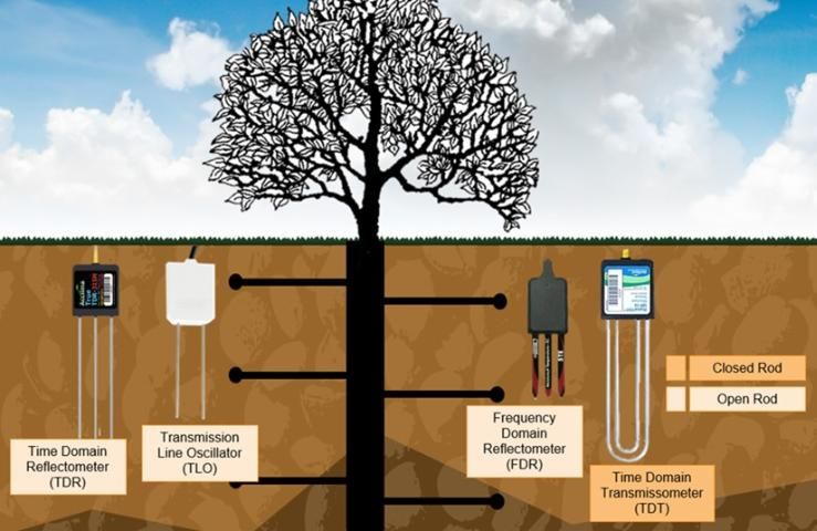
Based on their measurements, there are two types of SMSs: tensiometric, which emulate the suction that plant roots need to apply to take water from the soil, and volumetric based, which indirectly measure the volume of water in a unit of soil or volumetric water content (VWC). For more information on SMS types, see EDIS document BUL343, Field Devices For Monitoring Soil Water Content (https://edis.ifas.ufl.edu/ae266) (Muñoz-Carpena 2004). A volumetric type SMS relies on calibrated relationships between the traveling time of an electrical pulse emitted by the sensor and the water content of the surrounding soil. Volumetric based type SMSs are the most widely used sensors in Florida. Figure 1 shows an example of commonly used handheld SMSs for tree irrigation management in Florida.
There are multiple factors to consider when evaluating the suitability of a volumetric SMS for irrigation scheduling in Florida. These factors include adaptability for sandy soils, sensitivity to air gaps, temperature, salinity, precision and accuracy, and ease of sensor installation and maintenance. The SMS options in Figure 1 can be adapted for Florida fruit tree irrigation. Nevertheless, each SMS type has pros and cons. For example, although the TDT SMSs are well known to be among the most accurate SMSs in the market, they require a careful installation because their rods are in a closed loop. Because of this loop, users must double-check soil coverage inside the rods to ensure proper installation. In contrast, open-rod SMSs (light yellow in Figure 1) are relatively easy to install because they only need to be pushed into the soil; however, the readings are more sensitive to nearby objects such as rocks and soil. To select the most appropriate SMS for each situation, it is recommended to have preliminary information on soil type and variability, water source, and irrigation type.
Credit: Sandra Guzmán, UF/IFAS
In terms of precision and accuracy, most SMSs provide sufficient information to manage irrigation. Usually, the SMS readings displayed in a graphical form are a practical way to assess soil water status. More information on SMS data interpretation is available in Understanding Soil-Moisture Sensor Data (https://crec.ifas.ufl.edu/media/crecifasufledu/extension/extension-publications/2017/2017_July_sensor.pdf) (Schumann and Waldo 2017). In certain cases, mostly for research and regulation, the direct readings rather than the weekly graphs are preferred to facilitate the quantification of water used through the crop season. In those cases, it is important to verify the units in which the data are provided. For sandy soils, the maximum soil moisture is usually around 30% (or 0.30 m3/m3 based on the SMS type). If the SMS reading is higher than 30%—which could happen with Meter Group (previously Decagon) SMSs, for example—it might represent a relative value or an inaccurate reading. The user should request more information from the manufacturing company on how to interpret measurements when the readings are relative. Most SMSs are compatible with SDI-12 communication protocol. This protocol is supported by almost any modern data logger in case the user decides to have continuous readings.
Does the sensor require calibration?
Most SMSs are calibrated in the laboratory by the manufacturing company using generic soil types. However, UF/IFAS research shows that users would achieve increased sensor accuracy by performing additional site-specific calibrations. Soil type and physical properties, salinity, and air gaps are the primary factors that affect the accuracy of the readings. We recommend installing the SMS after a rain event or in a well-watered soil and examining the graphical trends for a week. Those trends will allow the user to identify changes in soil moisture across time. For field validation, soil samples can be collected for gravimetric moisture determination in a soil lab. The gravimetric readings can be compared with those from the SMS for calibration. Calibration processes are well documented, and we provide a list of related readings in the References section. If more information about SMS calibration requirements is required, the user may contact the SMS manufacturing company's technical support team or a local UF/IFAS irrigation specialist.
Do nearby objects affect an SMS reading?
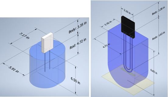
When installing an SMS, the irrigator can encounter many surrounding objects in the soil including rocks, primary and secondary roots, and even air gaps. To measure soil water, the electrical current in the SMS is averaged across a certain soil area near the SMS rods. This soil area is called sensing volume. Figure 2 shows the sensing volume for the TLO and TDT sensors, respectively. Ideally, the sensing volume should be free of objects. When rocks, roots, or other objects are inside the sensing volume, the SMS might provide readings that are lower than the actual field conditions. Avoid rocky locations or areas where roots are widespread. Use the following steps to perform an initial field assessment.
- Select the SMS installation site.
- Make an initial inspection of objects and materials that are visible across the soil surface.
- Make a hole 6 inches wide and 7 inches deep. These dimensions will serve for most SMSs (For the TDT type, the hole can be 3 inches wide instead of 6 inches).
- Make a visual inspection across the walls of the hole for rocks and other objects.
- Remove nearby objects, fill with soil any open areas, and install the SMS. Make sure the soil covers the rods completely.
Credit: Eric Herrera, UF/IFAS
Most manufacturing companies provide information about the sensing volume. The closer the rocks, roots, or other objects are to the SMS rods, the more inaccurate the measurement will be. The error introduced by these objects results in an underestimation of the volumetric water content because the objects influence the electrical signal coming from the sensor. Inaccurate readings might result in incorrect irrigation management.
In what position should the SMS be installed?
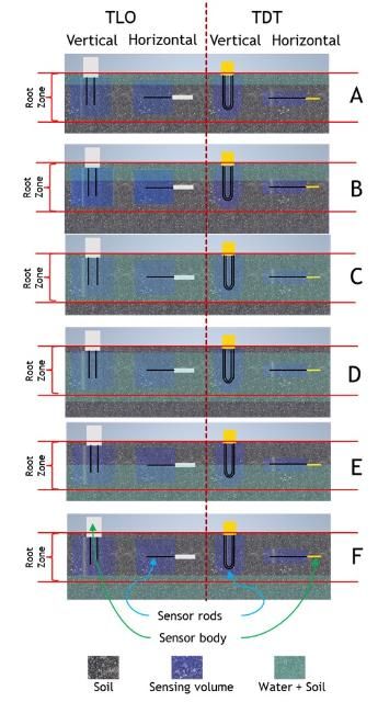
There are two common positions in which the SMSs can be installed: either horizontally or vertically. Figure 3 shows an example of installation positions for the TLO (left) and TDT SMS (right). After an irrigation or rain event, the vertically positioned sensor can register soil moisture earlier than the horizontally positioned sensor (Figure 3A, right). After some time (Figures 3B and 3C), both vertical and horizontal sensors register similar values. As the water moves downwards, the rods at the vertical installation are in contact with the soil water for a longer period of time (Figures 3E and 3F). Regardless of the position, the SMSs will read values based on the variations across the sensing volume. Other factors to consider include the number and location of sensors. It is common to assume that one SMS installed vertically is enough to characterize the movement of water across the root depth (considering depths of around 7 inches). However, it is recommended to have at least two SMSs per location for either vertical or horizontal installations. Some users install the shallowest SMS vertically and the deepest SMS horizontally. For vertical installations, the upper SMS (usually with rods 3–4 inches from the soil surface) will show the trends of water movement across the root system, and the lower SMS (usually installed 6 inches from the soil surface) will show water moving below the root zone or water table rises. If there is more than one soil layer across the root zone, there should be at least one SMS installed per layer.
Credit: Eric Herrera, UF/IFAS
Where should the sensor be located?
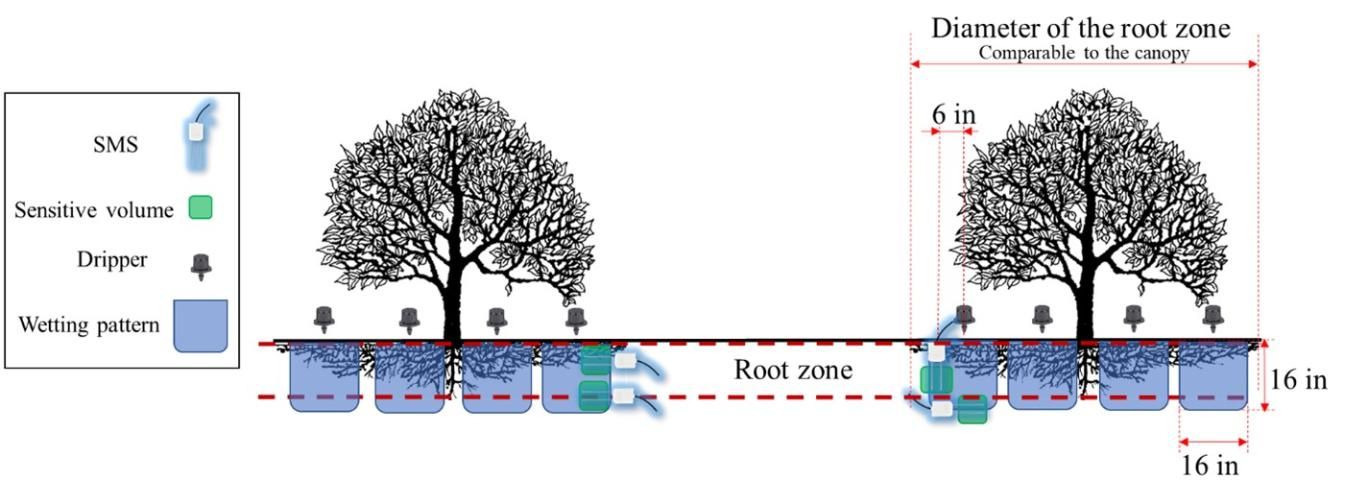
The SMS should be in an area that represents the average soil, plant, and irrigation conditions. For more information about the proper location, see Using Soil Moisture Sensors for Citrus Irrigation (http://citrusindustry.net/2018/07/10/using-soil-moisture-sensors-for-citrus-irrigation/) (Schumann et al. 2018) and Understanding Soil-Moisture Sensor Data (https://crec.ifas.ufl.edu/extension/trade_journals/2017/2017_July_sensor.pdf) (Schumann and Waldo 2017). The sensor should be completely buried in the soil, including the body area (Figure 2), and installed as close as possible to the tree roots without entering the sensitive volume (or no more than 1 foot from the end of the canopy). In terms of depth, it is recommended to install the SMS at least three inches from the soil surface. Additionally, the SMS should be located inside the irrigation wet pattern. The SMS installation differs according to the irrigation system used. For drip irrigation, the SMS should be located within 8 inches of the dripper. The closer the SMS is to the dripper, the better, as long as there is no interference from other components (e.g., main roots or rocks). When the SMS is outside of the dripper wetting pattern, it could underestimate the amount of soil water available for the trees. A proper SMS location would be around 6 inches from the dripper if we consider main roots, rocks, and the SMS sensitive volume. Figure 4 shows an example of an SMS installation when using drip irrigation, for both vertical and horizontal configurations.
Credit: Eric Herrera, UF/IFAS
For microsprinkler irrigation, there is a wider wetting pattern (see the blue area in Figure 5) and usually one microsprinkler for each tree. In this case, the location of the SMSs is determined primarily by the root depth and the uniformity of the irrigation system. The SMS should be in an area located close to both the main roots and the microsprinkler. A suggested SMS location is highlighted in yellow in Figure 5.
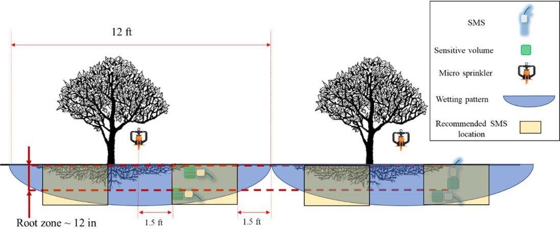
Credit: Eric Herrera, UF/IFAS
When installing an SMS, it is ideal to leave it as close as possible to the root system and minimize moving the device. If the SMS trends and readings are inconsistent, it could be because new, horizontally growing roots are intersecting the SMS sensing volume.
Finally, when placing SMS systems with telemetry, users may need to consider additional factors including cellphone and radio range to the remote station, length of the SMS cables connected to the data logger, and power sources. The maximum sensor cable length is around 2,000 feet for TLO and 190 feet for TDT. Before selecting cable length, make a detailed layout of the cable pathway and consider the conduit joints and intersections to allow calculating the required cable length before purchase and installation. Consider burying cables at least 2 inches deep and using a flexible hose or small-diameter conduit when crossing drainage swales, furrows, and bed tops. These safety measurements will help to protect the cables not only from animals but also from crop maintenance tools (tractors, shovels, etc.). After conduit tracks are installed in the field, double-check the cable length estimation before purchasing the sensors.
We recommend using SMS systems with telemetry. These systems provide reliable data that can be transmitted in real time to any device and make scheduling irrigation easier. Wireless communications are sometimes unpredictable, and the best way to manage them is usually by trial and error. Therefore, good communication and technical assistance from the manufacturing company are important. Proper SMS installation is critical for reliable readings and more efficient irrigation management.
References
Campbell Scientific. 2021. "Using a CS650 or a CS655, when should a soil-specific calibration be performed?" Accessed on January 12, 2021. https://www.campbellsci.com/faqs?v=1041
Muñoz-Carpena, R. 2004. Field Devices for Monitoring Soil Water Content. BUL343. Gainesville: University of Florida Institute of Food and Agricultural Sciences. https://edis.ifas.ufl.edu/ae266
Schumann, A., and L. Waldo. 2017. "Understanding Soil Moisture Sensor Data." Citrus Industry Magazine 8(July): 1–15. https://citrusindustry.net/2017/07/10/understanding-soil-moisture-sensor-data/
Schumann, A., L. Waldo, D. Kadyampakeni, R. Ferrarezi, and C. Oswalt. 2018. "Using Soil Moisture Sensors for Citrus Irrigation." Citrus Industry News. http://citrusindustry.net/2018/07/10/using-soil-moisture-sensors-for-citrus-irrigation/