Microirrigation systems can deliver water and nutrients at controlled frequencies directly to the plant's root zone. With microirrigation systems an extensive network of pipes is used to distribute water to emitters which discharge it in droplets, small streams or through mini-sprayers.
Over the last two decades, microirrigation systems continue to be used in trees and other horticultural crops because of their adaptability for both irrigation and freeze protection. Microirrigation, properly managed, offers several potential advantages over other methods of irrigation:
- Comparable water application uniformity.
- Improved water use efficiency.
- If scheduled properly, minimized deep percolation and runoff.
- Efficient delivery of fertilizer (fertigation) and other chemicals (chemigation) trough the irrigation system.
- Ability to irrigate land too steep for irrigation by other means.
The plugging of emitters is one of the most serious problems associated with microirrigation use. Emitter plugging can severely hamper water application uniformity.
Causes of Emitter Plugging
Emitter plugging can result from physical (grit), biological (bacteria and algae), or chemical (scale) causes. Frequently, plugging is caused by a combination of more than one of these factors.
Influence of the Water Source
The type of emitter plugging problems will vary with the source of the irrigation water. Water sources can be grouped into two categories: surface or ground water. Each of these water sources produce specific plugging characteristics.
Algal and bacterial growth are major problems associated with the use of surface water. Whole algae cells and organic residues of algae are often small enough to pass through the filters of an irrigation system. These algal cells can then form aggregates that plug emitters (Haman 1987c). Residues of decomposing algae can accumulate in pipes and emitters to support the growth of slime-forming bacteria. Surface water can also contain larger organisms such as moss, fish, snail, seeds, and other organic debris that must be adequately filtered to avoid plugging problems.
Groundwater, on the other hand, often contains high levels of minerals in solution that can precipitate and form scale. Water from shallow wells (less than 100 ft) often will produce plugging problems associated with bacteria; chemical precipitation is more common with deep wells (Knapp et al. 1986). Physical plugging problems are generally less severe with groundwater.
Physical
Sources of physical plugging problems include particles of sand and suspended debris that are too large to pass through the openings of emitters. Sand particles, which can plug emitters, are often pumped from wells. Water containing some suspended solids may be used with microirrigation systems if these suspended solids consist of clay-sized particles, and flocculation does not occur. Research has shown that using water with over 500 ppm suspended solids did not cause emitter plugging as long as the larger particles were filtered (Pitts 1985).
Under some conditions, however, clay will flocculate and form aggregates causing plugging. Unflocculated clay and silt-sized particles are normally too small to plug emitters. Turbidity is an indicator of suspended solids, but turbidity alone is not an accurate predictor of the plugging potential of a water source. Turbidity should be combined with a laboratory filtration test to measure plugging potential (Gilbert and Ford 1986).
Biological
A microirrigation system can provide a favorable environment for bacterial growth, resulting in slime buildup. This slime can combine with mineral particles in the water and form aggregates large enough to plug emitters. Certain bacteria can cause enough precipitation of manganese, sulfur, and iron compounds to cause emitter plugging. In addition, algae can be transported into the irrigation system from the water source and create conditions that may promote the formation of aggregates.
Emitter plugging problems are common when using water that has high biological activity and high levels of iron and hydrogen sulfide. This is a frequent problem in Florida, because iron and sulfur are common constituents of many Florida waters.
Soluble ferrous iron is a primary energy source for certain iron-precipitating bacteria (Gilbert and Ford 1986). These bacteria can attach to surfaces and oxidize ferrous iron to its insoluble ferric iron form. In this process, the bacteria create a slime that can form aggregates called ochre, which may combine with other materials in the microirrigation tubing and cause emitter plugging (Ford and Tucker 1975). Ochre deposits and associated slimes are usually red, yellow, or tan.
Sulfur slime is a yellow to white stringy deposit formed by the oxidation of hydrogen sulfide commonly present in shallow wells in Florida. Hydrogen sulfide (H2S) accumulation in groundwater is a process typically associated with reduced conditions in anaerobic environments. Sulfide production is common in lakes and marine sediments, flooded soils, and ditches; it can be recognized by the rotten egg odor. Sulfur slime is produced by certain filamentous bacteria that can oxidize hydrogen sulfide and produce insoluble elemental sulfur.
The sulfur bacteria problem can be minimized if there is not air-water contact until water is discharged from the system. Defective valves or pipe fittings on the suction side of the irrigation pump are common causes of sulfur bacteria problems (Ford and Tucker 1975). If a pressure tank is used, the air-water contact in the pressure tank can lead to bacterial growth in the tank, clogging the emitter. The use of an air bladder or diaphragm to separate the air from the water should minimize this problem.
Chemical
Water is often referred to as the universal solvent since almost everything is soluble in it to some extent. The solubility of a given material in water is controlled by variations in temperature, pressure, pH, redox potential, and the relative concentrations of other substances in solution. Three gases (oxygen, carbon dioxide, and hydrogen sulfide) are important in determining the solubility characteristics of water. These gases are very reactive in water, and they determine to a significant extent the solubility of minerals within a given water source.
In order to predict what might cause chemical plugging of microirrigation system emitters, the process of mineral deposition must be understood. Carbon dioxide gas (CO2) is of particular importance in the dissolution and deposition of minerals. Water absorbs some CO2 from the air, but larger quantities are absorbed from decaying organic matter as water passes through the soil. Under pressure, as is groundwater, the concentration of CO2 increases to form carbonic acid. This weak acid can readily dissolve mineral compounds such as calcium carbonate to form calcium bicarbonate which is soluble in water. This process allows calcium carbonate to be dissolved, transported, and under certain conditions, again redeposited as calcium carbonate.
Calcium carbonate is the most common constituent of scale. Calcite, aragonite, and vaterite are mineral forms of calcium carbonate that have been found in carbonate scale. Calcite is formed at temperatures common within microirrigation systems, and is the most common and stable of the mineral forms.
Calcium minerals occur extensively in the form of limestone and dolomite (magnesium-calcium carbonate). Calcite is the principal constituent of limestone, and occurs in many calcareous metamorphic rocks such as marble. Therefore, it is not surprising to encounter calcium carbonate in solution in almost all surface and ground waters, especially in Florida where much of the groundwater is pumped from large underlying limestone formations. As groundwater passes through these limestone formations it dissolves the limestone and carries calcium carbonate with it.
Chemical plugging usually results from precipitation of one or more of the following minerals: calcium, magnesium, iron, or manganese. The minerals precipitate from solution and form encrustations (scale) that may partially or completely block the flow of water through the emitter. Water containing significant amounts of these minerals and having a pH greater than 7 has the potential to plug emitters. Particularly common is the precipitation of calcium carbonates, which is temperature and pH dependent. An increase in either pH or temperature reduces the solubility of calcium in water, and results in precipitation of the mineral.
When groundwater is pumped to the surface and discharged through a microirrigation system, the temperature, pressure, and pH of the water often changes. This can result in the precipitation of calcium carbonates or other minerals to form scale on the inside surfaces of the irrigation system components. A simple test for identifying calcium scale is to dissolve it with vinegar. Carbonate minerals dissolve and release carbon dioxide gas with a fizzing, hissing sound known as effervescence.
Iron is another potential source of mineral deposit that can plug emitters. Iron is encountered in practically all soils in the form of oxides (Cowan 1976), and it is often dissolved in groundwater as ferrous bicarbonate. When exposed to air, soluble ferrous bicarbonate oxidizes to the insoluble or colloidal ferric hydroids and precipitates. The result is commonly referred to as 'red water,' which is sometimes encountered in farm irrigation wells. Manganese will sometimes accompany iron, but usually in lower concentrations.
Hydrogen sulfide is present in many wells in Florida. Precipitation problems will generally not occur when hard water, which contains large amounts of hydrogen sulfide, is used. Hydrogen sulfide will minimize the precipitation of calcium carbonate (CaC03) because of its acidity.
Fertigation
Fertigation is the application of plant nutrients through an irrigation system by injection into the irrigation water. Fertilizers injected into a microirrigation system may contribute to plugging. Field surveys have indicated considerable variation in fertilizer solubility for different water sources (Ford 1977). To determine the potential for plugging problems from fertilizer injection, the following test can be performed:
- Add drops of the liquid fertilizer to a sample of the irrigation water so that the concentration is equivalent to the diluted fertilizer that would be flowing in the lateral lines.
- Cover and place the mixture in a dark environment for 12 hours.
- Direct a light beam at the bottom of the sample container to determine if precipitates have formed. If no apparent precipitation has occurred, the fertilizer source will normally be safe to use in that specific water source (Gilbert and Ford 1986).
Prevention of Emitter Plugging
A properly designed microirrigation system should include preventive measures to avoid emitter plugging. Differences in operating conditions and water quality do not allow a standardized recommendation for all conditions. In general, however, the system should include the following:
- a method of filtering the irrigation water.
- a means of injecting chemicals into the water supply.
- in some cases a settling basin to allow aeration and the removal of solids.
- equipment for flushing the system.
Prevention of plugging can take two basic approaches: 1) removing the potential source of plugging from the water before it enters the irrigation system; or 2) treating the water to prevent or control chemical and biological processes from occurring. Both approaches will be discussed. In many cases, a combination of both approaches will be applicable.
Water Quality Analysis
Knowing the quality of proposed irrigation water is necessary before designing a microirrigation system. Water quality analyses are performed at water testing laboratories (e.g. UF/IFAS Soil and Water Testing Laboratory, Gainesville). A water analysis specifically for microirrigation should be requested. The analysis should include the factors listed in Table 1. If the source is groundwater from a relatively deep well (over 100 ft), analysis for bacteria population may be omitted. Conversely, if the source is surface water, hydrogen sulfide will not be present and can be omitted. Table 1 provides concentration levels for evaluating the water quality analysis in terms of the potential for emitter plugging.
A water quality analysis usually lists electrical conductivity in micromhos per centimeter (mho/cm). To estimate parts per million (ppm) dissolved solids as shown in Table 1, multiply mho/cm by 0.64. For example, if the electric conductivity meter reads 1000 mho/cm, then dissolved solids can be estimated as 640 ppm.
Hardness is primarily a measure of the presence of calcium (Ca) and magnesium (Mg), and is another indicator of the plugging potential of a water source. If Ca and Mg are given in ppm rather than hardness, hardness can be estimated from the relationship shown in Equation 1: where calcium (Ca) and magnesium (Mg) are given in milligrams per liter (mg/L or ppm).
Equation 1:
Hardness = (2.5 X Ca) + (4.1 X Mg)
Note that 1 mg/L equals 1 ppm. If the analysis lists the Ca and Mg concentrations in milliequivalents per liter (meq/l), they can be converted to ppm by the factors shown in Equation 2: This method of estimating hardness may give results that vary somewhat from results obtained for total hardness by laboratory methods. However, the estimate is normally adequate for use in Table 1.
Equation 2:
Ca (meq/L) X 20 = Mg (ppm)
Mg (meq/L) X 12 = MG (ppm)
Filters for Prevention of Physical Plugging
Many types of microirrigation filter systems that will perform adequately are available commercially. Important factors to consider in selecting a filtering method are emitter design and quality of the water source. Consider the emitter's minimum passageway diameter when selecting the filter mesh size. Filters should be sized according to the emitter manufacturer's recommendations or, in the absence of manufacturer's recommendations, to remove any particles larger than one-tenth the diameter of the smallest opening in the emitter flow path.
Screen filters come in a variety of shapes and sizes. A typical design is shown in Figure 1. Screen material may be slotted PVC, perforated stainless steel, or synthetic or stainless steel wire. Mesh size—the number of openings per inch—determines the fineness of the material filtered.

Surface water sources should have a coarse screen filter installed on the pump inlet (suction) line to block trash and large debris. To avoid floating debris, the pump inlet should be located two feet below the water surface but suspended above the bottom.
Screen filters remove only small amounts of sands and organic material before clogging and causing a flow rate reduction. Two or more filters installed in parallel will increase the time between screen cleanings. Screen cleaning can be a manual or automatic operation.
Wafer (disc) filters consist of a stack of washers that provide a filtering surface area for the water to pass over as it flows through the filter (see Figure 2). These filters are sized based on the equivalent screen mesh filter size. They also require periodic cleaning. Some manufacturers provide an automatic backflush feature. Wafer filters provide more filter surface area than screen filters of the same size.

Media (sand) filters are available with the capacity to efficiently remove most types of physical plugging sources (see Figure 3). These filters will remove colloidal and organic material usually present in surface waters. The size and type of media used determines the degree of filtration. The finer the media, the smaller the particle size that will be removed. Table 2 shows the relationship between sand grade and screen mesh size.
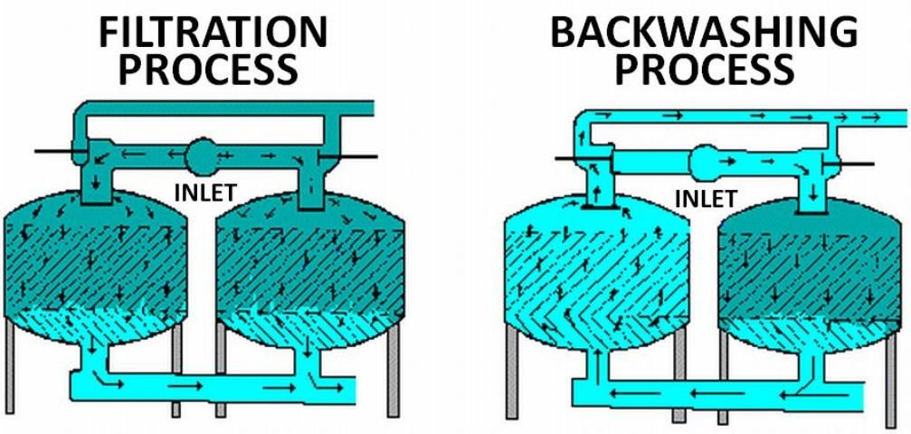
Size of the media filter required is determined by the flow rate of the system, and is measured by the top surface area of the filter. Media filters should be sized to provide a minimum of one square foot of top surface area for every 20 GPM of flow, or as the manufacturer recommends.
Filters are cleaned by reversing the direction of water flow through them; this procedure is called backwashing. Backwashing can be manual or automatic, on a set time interval or at a specific pressure drop. When using a media filter, install it with an additional screen filter (200-mesh or manufacturer's recommendation) downstream to prevent the transport of sand to the irrigation system during the backwash procedure. For more information on the selection, operation and maintenance of media filters, see Agricultural Engineering EDIS publication WI008, Media Filters for Trickle Irrigation in Florida.
Vortex or centrifugal filters (Figure 4) effectively remove sand and larger particles, but are not effective at removing algae, very fine precipitates, and other light-weight materials. This type of filter should be used as the first filter if the water source is a sand pumping well or a fast-moving stream. It should be followed by a media and screen filter for surface water sources, or screen or wafer filter for well water.
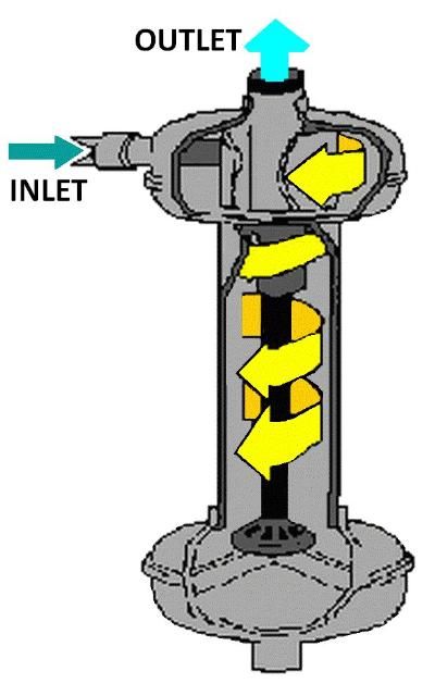
Settling Ponds
In addition to filtration, the quality of water with high levels of solids can be improved with settling ponds or basins to remove large inorganic particles. Settling ponds can also be used for aeration of groundwater containing high amounts of iron or manganese.
Experiments have shown that a ferrous iron content as low as 0.2 ppm can contribute to iron deposition (Gilbert and Ford 1986). Iron is very common in shallow wells in many parts of Florida, but it can often be economically removed from irrigation water by aeration (or by some other means of oxidation), followed by sedimentation and/or filtration.
Existing ponds can sometimes be used as settling basins. They need not be elaborate structures; however, settling basins should be accessible for cleaning, and large enough that the velocity of the flowing water is sufficiently slow for particles to settle out. Experience based on municipal sedimentation basins indicates that the maximum velocity should be limited to 1 foot per second.
A settling basin should be designed to remove particles having equivalent diameters exceeding 75 microns, which corresponds to the size of a particle removed by a 200-mesh screen filter. The basin works on the principle of sedimentation, which is the removal of suspended particles that are heavier than water by gravitational settling. Materials held in suspension due to the velocity of the water can be removed by lowering the velocity. In some cases, materials that are dissolved in solution oxidize (through exposure to a free air surface), precipitate, and flocculate to form aggregates large enough to settle out of the water.
Settling ponds are also recommended when the irrigation water source is a fast-moving stream. Velocity of the water is slowed in the settling pond, thus allowing many particles to settle out.
Flushing
To minimize sediment build up, regular flushing of drip irrigation pipelines is recommended. Valves large enough to allow sufficient velocity of flow should be installed at the ends of mains, submains, and manifolds. Also, allowances for flushing should be made at the ends of lateral lines. Begin the flushing procedure with the mains, then proceed to submains, manifolds, and finally to the laterals. Flushing should continue until clean water runs from the flushed line for at least two minutes. A regular maintenance program of inspection and flushing will help significantly in preventing emitter plugging.
To avoid plugging problems when fertigating, it is best to flush all fertilizer from the lateral lines prior to shutting the irrigation system down.
Chemical Treatment
Chemical treatment is often required to prevent emitter plugging due to microbial growth and/or mineral precipitation. The attachment of inorganic particles to microbial slime is a significant source of emitter plugging. Chlorination is an effective measure against microbial activity (Ford 1977; Ford 1979a,b,c; Tyson and Harrison 1985). Use chlorine and all other chemicals only according to label directions. Acid injection can remove scale deposits, reduce or eliminate mineral precipitation, and create an environment unsuitable for microbial growth (Cowan 1976).
Chlorine Injection
Chlorination is the most common method for treating bacterial slimes. If the microirrigation system water source is not chlorinated, it is a good practice to equip the system to inject chlorine to suppress microbial growth. Since bacteria can grow within filters, chlorine injection should occur prior to filtration.
Liquid sodium hypochlorite (NaOCl)—laundry bleach—is available at several chlorine concentrations. The higher concentrations are often more economical. It is the easiest form of chlorine to handle and is most often used in drip irrigation systems. Powdered calcium hypochlorite (CaCOCl2), also called High Test Hypochlorite (HTH), is not recommended for injection into microirrigation systems since it can produce precipitates that can plug emitters, especially at high pH levels (Tyson and Harrison 1985).
The following are several possible chlorine injection schemes:
- Inject continuously at a low level to obtain 1 to 2 ppm of free chlorine at the ends of the laterals.
- Inject at intervals (once at the end of each irrigation cycle) at concentrations of 20 ppm and for a duration long enough to reach the last emitter in the system.
- Inject a slug treatment in high concentrations (50 ppm) weekly at the end of an irrigation cycle and for a duration sufficient to distribute the chlorine through the entire piping system.
The method used will depend on the growth potential of microbial organisms, the injection method and equipment, and the scheduling of injection of other chemicals. Ford (1979c) developed a key that recommends chlorine injection rates for Florida conditions and irrigation systems.
The amount of liquid sodium hypochlorite required for injection into the irrigation water to supply a desired dosage in parts per million can be calculated by the simplified method in Equation 3: For more detailed information on injection rates, volumes and durations, the reader is referred to Clark et al. (1988).
Equation 3:
I = (0.006 X P X Q)/m
where,
I = gallons of liquid sodium hypochlorite injected per hour,
P = parts per million desired,
Q = system flow rate in gpm,
m = percent chlorine in the source, normally 5.25% or 10%.
When chlorine is injected, a test kit should be used to check to see that the injection rate is sufficient. Color test kits (D.P.D.) that measure 'free residual' chlorine, which is the primary bactericidal agent, should be used. The orthotolidine-type test kit, which is often used to measure total chlorine content in swimming pools, is not satisfactory for this purpose. D.P.D. test kits can be purchased from irrigation equipment dealers. Check the water at the outlet farthest from the injection pump. There should be a residual chlorine concentration of l to 2 ppm at that point. Irrigation system flow rates should be closely monitored, and action taken (chlorination) if flow rates decline.
Chlorination for bacterial control is relatively ineffective above pH 7.5, so acid additions may be necessary to lower the pH to increase the biocidal action of chlorine for more alkaline waters. This may be required when the water source is the Floridian aquifer.
Since sodium hypochlorite can react with emulsifiers, fertilizers, herbicides, and insecticides, bulk chemicals should be stored in a secure place according to label directions.
Acid Treatment
Acid can be used to lower the pH of irrigation water to reduce the potential for chemical precipitation and to enhance the effectiveness of the chlorine injection. Sulfuric, hydrochloric, and phosphoric acid are all used for this purpose (Kidder and Hanlon 1985). Acid can be injected in much the same way as fertilizer; however, extreme caution is required. The amount of acid to inject depends on how chemically base (the buffering capacity) the irrigation water is and the concentration of the acid to be injected. One milliequivalent of acid completely neutralizes one milliequivalent of bases.
If acid is injected on a continuous basis to prevent calcium and magnesium precipitates from forming, the injection rate should be adjusted until the pH of the irrigation water is just below 7.0. If the intent of the acid injection is to remove existing scale buildup within the microirrigation system, the pH will have to be lowered more (Cowen and Weintritt 1976). The release of water into the soil should be minimized during this process since plant root damage is possible. An acid slug should be injected into the irrigation system and allowed to remain in the system for several hours, after which the system should be flushed with irrigation water. Acid is most effective at preventing and dissolving alkaline scale. Avoid concentrations that may be harmful to emitters and other system components.
Phosphoric acid, which is also a fertilizer source, can be used for water treatment. Some microirrigation system operators use phosphoric acid in their fertilizer mixes. Caution is advised if phosphoric acid is used to suppress microbial growth. Care should be used with the injection of phosphoric acid into hard water since it may cause the precipitation of calcium carbonate at the interface between the injected chemical and the water source.
For safety, dilute the concentrated acid in a non-metal, acid-resistent mixing tank prior to injection into the irrigation system. When diluting acid, always add acid to water, never water to acid. The acid injection point should be beyond any metal connections or filters to avoid corrosion. Flushing the injection system with water after the acid application is a good practice to avoid deterioration of components in direct contact with the acid.
Acids and chlorine compounds should be stored separately, preferably in epoxy-coated plastic or fiberglass storage tanks. Acid can react with hypochlorite to produce chlorine gas and heat; therefore, the injection of acid should be done at some distance (2 feet), prior to the injection of chlorine. This allows proper mixing of the acid with the irrigation water before the acid encounters the chlorine.
Hydrochloric, sulfuric, and phosphoric acids are all highly toxic. Always wear goggles and chemical-resistant clothing whenever handling these acids. Acid must be poured into water; never pour water into acid.
Scale Inhibitors
Scale inhibitors, such as chelating and sequesting agents, have long been used by other industries. A number of different chemicals are being marketed for use in microirrigation systems to prevent plugging. Many of these products contain some form of inorganic polyphosphate that can reduce or prevent precipitation of certain scale-forming minerals. These inorganic phosphates do not stop mineral precipitation, but keep it in the sub-microscopic range by inhibiting its growth. Probably the most commonly used of these materials is sodium hexametaphosphate—as little as 2 ppm can hold as much as 200 ppm calcium bicarbonate in solution (Cowan and Weintritt 1976).
Sodium hexametaphosphate is not only effective against alkaline scale, but also forms complexes with iron and manganese and can prevent depositions of these materials. Although the amount of phosphate required to prevent iron deposits depends on several factors, a general recommendation is 2 to 4 ppm phosphate for each ppm of iron or manganese (Cowen and Weintritt, 1976).
These phosphates are relatively inexpensive, readily soluble in water, nontoxic, and effective at low injection rates.
Pond Treatment
Algae problems which often occur with surface water sources such as a pond can be effectively treated with copper sulfate (CuS04). Dosages of 1 to 2 ppm (1.4 to 2.7 pounds per acre foot) are sufficient and safe to treat algae growth. Copper sulfate should be applied when the pond water temperature is above 60°F. Treatments may be repeated at 2 to 4-week intervals, depending on the nutrient load in the pond. Copper sulfate should be mixed into the pond (i.e., sprinkled into the wake of a boat). The distribution of biocides into surface water must be in compliance with EPA regulations.
Copper sulfate can be harmful to fish if alkalinity, a measure of the water's capacity to neutralize acid, is low. Alkalinity is measured volumetrically by titration with H2S04 and is reported in terms of equivalent CaC03. Table 3 provides a reference for determining rates to add copper sulfate given different alkalinity levels. Repeated use of copper sulfate can result in the buildup to levels toxic for plants.
Injection Methods
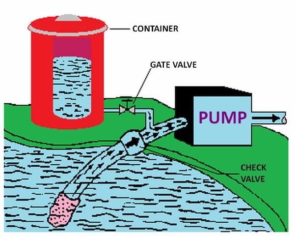
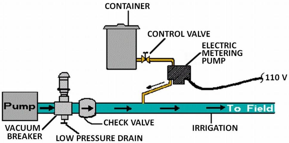
Several types of injection systems, available commercially through irrigation equipment suppliers, are commonly used with microirrigation: venturi, pressurized mixing tank, pump suction line method, and metering pumps (see Figures 5 through 8). Whichever method is used, there must be some way of controlling injection rates. Figure 5 shows a venturi injector in which the injection rate depends upon the creation of a 'low' pressure area as water flows through a constriction in the line. Since injection is based on the pressure differential that results, the rate of injection depends on pressure, flow, and the level of solution in the supply tank. Figure 6 shows a pressurized mixing tank where the solution is placed in a flexible membrane. Water entering the supply tank displaces solution from the membrane into the line. The injection rate is controlled by adjusting valves both on the main line and from the solution supply tank.
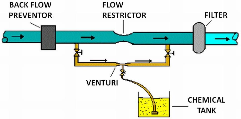
The pump suction line method is shown in Figure 7. With this method the pump must be resistant to any chemical that is to be injected. Because of backflow prevention regulations, this method is only permissible under certain conditions. Figure 8 shows a metering injection pump. These are often positive displacement injectors which rely on either a diaphragm or a piston-driven pump which produces a higher pressure in the chemical injection line than that in the irrigation pipeline. The injection rate can be very precisely controlled with this method, and it is recommended when a constant level of chemical concentration must be maintained in the system supply line such as when pesticides are injected.
Backflow Prevention
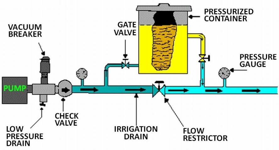
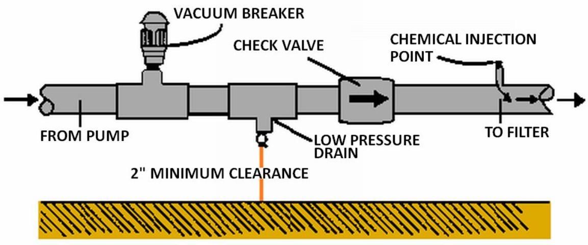
To ensure that the water source does not become contaminated, Florida law, EPA regulations, and county and municipal codes require backflow prevention assemblies on all irrigation systems injecting chemicals into irrigation water. For detailed information on these requirements, the reader is again referred to UF/IFAS Extension Bulletin 217. Appropriate backflow prevention should include the following setup:
- a check valve upstream from the injection device to prevent backward flow.
- a low pressure drain to prevent seepage past the check valve.
- a vacuum relief valve to ensure a siphon cannot develop.
- a check valve on the injection line.
Figure 9 shows the proper arrangement of equipment. If an externally-powered metering pump is used for injection, it should be electrically interlocked with the irrigation pump. This interlock should not allow the injection pump to operate unless the irrigation pump is operating. If irrigation water is being used from municipal or other public water supply systems, special backflow precautions must be taken.
Summary
- Emitter plugging can occur from physical, biological and chemical causes.
- A water quality analysis is vital to the proper design and operation of the microirrigation system.
- Every microirrigation system needs some method of filtration.
- Regular flushing of the lateral and main lines will help to prevent plugging.
- Most microirrigation systems will require a method of chemical treatment of the water source, and a backflow prevention system will also be required.
References
Cowan, J.C. and D.J. Weintritt. 1976. Water-formed Scale Deposits. Gulf Publishing Co. Houston TX.
Dupress, H.K. and J.V. Huner. 1984. Third Report of the Fish Farmer. United States Department of Interior, Fish and Wildlife Service. PP. 202. Washington, D. C.
Fereres, Elias. 1981. Drip Irrigation Management. Leaflet 21259. Division of Agriculture, University of California.
Ford, H.W. and D.P.H. Tucker. 1975. Blockage of Drip Irrigation Filters and Emitters by Iron-Sulfur- Bacterial Products. Hort Science 10 (1): 62-64.
Ford, H.W. 1979a. The Present Status of Research on Iron Deposits in Low Pressure Irrigation Systems. Fruit Crops Mimeo Report FC 79-3. Gainesville: University of Florida Institute of Food and Agricultural Sciences.
Ford, H.W. 1979b. The Use of Chlorine in Low Pressure Systems Where Bacterial Slimes are a Problem. Fruit Crops Mimeo Report FC 79-5. Gainesville: University of Florida Institute of Food and Agricultural Sciences.
Ford, H.W. 1979c. A Key for Determining the Use of Sodium Hypochlorite (Liquid Chlorine) to Inhibit Iron and Slime Clogging of Low Pressure Irrigation Systems in Florida. Lake Alfred, CREC Research Report CS 79-3. Gainesville: University of Florida Institute of Food and Agricultural Sciences.
Ford, H.W. 1977. Controlling Certain Types of Slime Clogging in Drip/Trickle Irrigation Systems. Proceedings of the 7th International Agricultural Plastics Congress, San Diego, California.
Ford, H.W. 1987. Iron Ochre and Related Sludge Deposits in Subsurface Drain Lines. Cir. 671. Gainesville: University of Florida Institute of Food and Agricultural Sciences.
Gilbert, R.G and H.W. Ford. 1986. Operational Principles. Chapter 3. Trickle Irrigation for Crop Production. (ED. Nakayama and Bucks) Elsevier Science Publishers. Amsterdam, Netherlands.
Haman, D.Z., A.G. Smajstrla and F.S. Zazueta. 1987a. Settling Basins for Trickle Irrigation in Florida. AE-65. Gainesville: University of Florida Institute of Food and Agricultural Sciences.
Haman, D.Z., A.G. Smajstrla and F.S Zazueta. 1987b. Media Filters for Trickle Irrigation in Florida. AE-57. Gainesville: University of Florida Institute of Food and Agricultural Sciences.
Haman, D.Z., A G. Smajstrla and F.S. Zazueta 1987c. Water Quality Problems Affecting Microirrigation in Florida. Agricultural Engineering Extension Report 87-2. Gainesville: University of Florida Institute of Food and Agricultural Sciences.
Haman, D.Z., A.G. Smajstrla and F.S. Zazueta. 1988. Screen Filters for Irrigation Systems. AE-61. Gainesville: University of Florida Institute of Food and Agricultural Sciences.
Knapp, M.S., W.S. Burns and T.S. Sharp. 1986. Preliminary Assessment of the Groundwater Resources of Western Collier County, Florida. Technical Publication #86-1, South Florida Water Management District.
Nakayama, F.S. and D.A. Bucks. 1986. Trickle Irrigation for Crop Production. Elsevier Science Publishers. Amsterdam, Netherlands.
Pitts, D.J., J.A. Ferguson and J.T. Gilmour. 1985. Plugging Characteristics of Drip-Irrigation Emitters Using Backwash from a Water-Treatment Plant. Bulletin 880, Arkansas Agricultural Experiment Station, University of Arkansas, Fayetteville.
Pitts, D.J. and P.L. Tacker. 1986. Trickle Irrigation: Causes and Prevention of Emitter Plugging. MP 271, Cooperative Extension Service, University of Arkansas.
Smajstrla, A.G., D.Z. Haman and F.S. Zazueta. 1986. Chemical Injection (Chemigation) Methods and Calibration. Agricultural Engineering Extension Report 85-22. Gainesville: University of Florida Institute of Food and Agricultural Sciences.
Smajstrla, A.G., D.S. Harrison, W.J. Becker, F.S. Zazueta and D.Z. Haman. 1988. Backflow Prevention Requirements for Florida Irrigation Systems. Bulletin 217. Gainesville: University of Florida Institute of Food and Agricultural Sciences.
Smajstrla, A.G. 1988. Backflow Requirements When Using Public Water Supplies. Bulletin 248. Gainesville: University of Florida Institute of Food and Agricultural Sciences.
Todd, D.K 1980. Groundwater Hydrology. p. 282. John Wiley and Sons, N.Y.
Tyson, A.W. and K.A. Harrison. 1985. Chlorination of Drip Irrigation Systems to Prevent Emitter Clogging. Misc. Publ. 183. Cooperative Extension Service, University of Georgia.