In Florida, greenhouse temperatures can easily exceed 100°F during the summer if they are not equipped with active cooling systems. Such high temperatures reduce crop quality and worker productivity. Evaporative cooling is the most common method for reducing the temperature inside a greenhouse, but it has limitations in our hot, humid climate. Air conditioning or refrigeration systems can be used, but their installation and operating costs are usually prohibitive.
Evaporative Cooling
Evaporative cooling is a process that reduces air temperature by evaporation of water into the airstream. As water evaporates, energy is lost from the air, causing its temperature to drop. Two temperatures are important when dealing with evaporative cooling systems—dry bulb temperature and wet bulb temperature. We usually think of dry bulb temperature as air temperature. It is the temperature measured by a regular thermometer exposed to the airstream. Wet bulb temperature is the lowest temperature that can be reached by the evaporation of water only. It is the temperature you feel when your skin is wet and exposed to moving air. Unlike dry bulb temperature, wet bulb temperature is an indication of the amount of moisture in the air.
Wet bulb temperatures can be determined by checking with your local weather station or by investing in an aspiration psychrometer, a sling psychrometer, or an electronic humidity meter. Wet bulb psychrometers consist of two thermometers exposed to the same airstream. The end of one thermometer is covered by a wetted wick. As the water in the wick evaporates, the temperature of the thermometer decreases to the wet bulb temperature. The other thermometer is exposed directly to the airstream and measures the dry bulb temperature. The difference between a sling psychrometer and an aspiration psychrometer is the way the airstream is provided. A sling psychrometer is mounted on a swiveled handle and whirled rapidly, while an aspiration psychrometer uses a small fan to provide air movement.
Relative humidity is a more common term for measuring the amount of moisture in the air. Handheld electronic humidity meters that display relative humidity are more convenient than wet bulb psychrometers. However, wet bulb temperature is a more useful measurement for evaporative cooling systems because it directly determines the temperature to which air can be cooled by evaporative cooling alone. Some electronic humidity meters have an option to display wet bulb temperatures. Even if a humidity meter does not display wet bulb temperature, tables and graphs known as psychrometric charts are available to calculate wet bulb temperature based on the dry bulb temperature and relative humidity. Software packages are also available to calculate wet bulb temperatures. It is important to remember that electronic humidity meters frequently drift out of calibration and should be checked against standards on a regular basis.
The best time to measure wet bulb temperature to calculate the potential cooling performance of the evaporative cooling system is in the afternoon. This is when dry bulb temperature is at its peak because solar radiation and outside temperatures are highest. This is also when the difference between dry bulb temperature and wet bulb temperature is greatest and there is maximum potential for cooling. Afternoon wet bulb temperatures during the summer in Florida often reach 79–80°F. With an efficient, well-managed system, it should be possible to reduce the temperature of the air entering the greenhouse to within 3–4°F of the wet bulb temperature. Keep in mind that this will not be the temperature in all areas of the greenhouse. As the air moves across the greenhouse to the exhaust fans, it will pick up solar heat. As a result, the exhausted air will likely be 7–8°F higher than the entering air. In a poorly managed system, the temperature of the exhausted air could exceed the ambient air temperature even more.
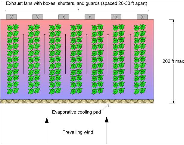
The basis of any evaporative cooling system is the evaporation of water into an airstream. The most common way of accomplishing evaporative cooling in a greenhouse is with a fan and pad system (Figure 1).
Credit: Erin G. Webb
High-pressure fog systems are also used to cool greenhouses. These fog systems can be designed and operated to maintain more uniform temperatures and humidities than fan and pad systems. Fog systems are more expensive than fan and pad systems, but they can be the best method of evaporative cooling when uniform temperatures and high humidity levels are needed.
Fan and Pad Evaporative Cooling Systems
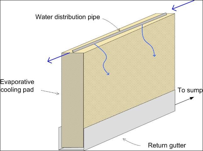
Fan and pad systems consist of exhaust fans at one end of the greenhouse and a pump circulating water through and over a porous pad (Figure 2) installed at the opposite end of the greenhouse.
Credit: Erin G. Webb
If all vents and doors are closed when the fans operate, air is pulled through the wetted pads and water evaporates. As each gallon of water evaporates, the water absorbs 8,100 BTU of heat energy from the air during the change from liquid to vapor. Removing energy from the air lowers the temperature of the air being introduced into the greenhouse.
The air will be at its lowest temperature immediately after passing through the pads. As the air moves across the greenhouse to the fans, the air picks up heat from solar radiation, plants, and soil, so the temperature of the air gradually increases. The resulting temperature increase as air moves down the greenhouse produces a temperature gradient across the length of the greenhouse, with the pad side being the coolest and the fan side being the warmest.
Temperature Gradient
The temperature increase across a greenhouse is hard to predict because it is affected by many variables. These include bench arrangements, physical obstructions to the movement of air across the greenhouse, percentage of floor area covered by plants, and floor material (i.e., bare soil or concrete). The roof configuration can also influence the temperature increase. Experience has shown that air may heat up as rapidly as 1°F every 10 feet as it moves across the greenhouse on sunny summer days. The slower the air movement, the greater the temperature increase.
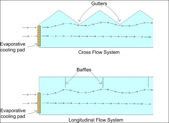
The increase in temperature across the greenhouse at plant level is most important. In most systems, the air tends to diverge upward at an angle of approximately 7° above horizontal, or roughly 1 foot in 8 feet. The upper layer of cooled air rises toward the peak of the building above the crop zone and thus does little to cool the plants. In a crossflow arrangement of gutter-connected greenhouses, the gutters serve as baffles and tend to keep the cool air at crop level. In longitudinal flow arrangements where the airflow is lengthwise down the greenhouse, baffles should be installed that extend from the roof down to just above the top of the crop. The baffles should be transparent, spaced about 30 feet apart, and mounted in a fixed position (Figure 3).
Credit: Erin G. Webb
Systems Efficiency
If the efficiency of the evaporative cooling system is known, the temperature of air exiting a cooling pad can be calculated by the following equation.
Tcool=Tout - (% efficiency)(Tout - Twb)
where: Tcool = temperature of air exiting cooling pad
Tout = temperature of the outside air
Twb=wet bulb temperature of the outside air
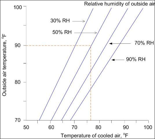
A well-designed and properly installed and operated evaporative cooling system may have an efficiency of up to 85%. Figure 4 shows the temperature of the cooled air exiting an 85% efficient evaporative cooling pad as a function of the outside air for several relative humidity values. With an outdoor relative humidity of 50% and temperature of 90°F, this evaporative cooling system reduces the temperature to 76.5°F.
Credit: Erin G. Webb
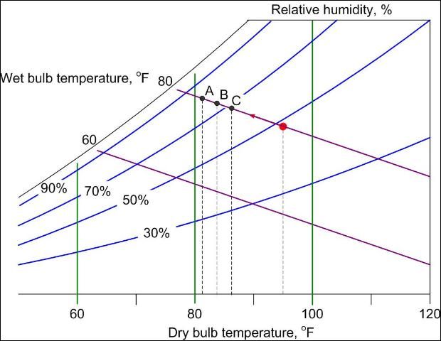
The difference between dry bulb temperature and wet bulb temperature is referred to as the wet bulb depression. If your system is 85% efficient, then the air entering the greenhouse is the outside dry bulb temperature minus 85% of the wet bulb depression. Figure 5 shows what happens to air with a dry bulb temperature of 95°F and with a wet bulb temperature of 80°F that is cooled using an evaporative cooling pad. If the pad is 85% efficient, the air is cooled to point A or 82°F. If the pad is 70% efficient, the air is cooled to point B or 84.5°F. The air is cooled to point C or 87.5°F if the pad is 50% efficient.
Credit: Erin G. Webb
Factors That Influence Fan and Pad Evaporative Cooling Systems
Operational Considerations
It is very important to keep the building as tight as possible to push entering air through the pads. Make sure that all doors and other openings are kept closed when not in use and that any gaps in the greenhouse coverings are sealed. If not, air will be pulled through these openings rather than through the cooling pad. The efficiency of a fan and pad cooling system depends on air moving through the cooling pads.
House Location and Orientation
Orientation of the greenhouse relative to other buildings or structures and to prevailing summer winds influences the efficiency of operation. Greenhouse location and orientation should be considered when selecting fan arrangements and locations of the fans and pads.
Type of Cooling Pad
The most widely used type of pad material is corrugated cellulose that has been impregnated with wetting agents and insoluble salts to help resist rot. These pads are expensive but, when properly maintained, do an excellent job of cooling air. With proper maintenance, corrugated pads should have a lifetime of ten years.
Aspen pads were commonly used in the past, and some are still in service. However, the life of an aspen pad under Florida conditions is usually short. Aspen pads are very susceptible to algae infestation that leads to rotting and compaction. This makes it difficult to keep a system operating efficiently without frequent and costly pad replacements.
Other pad materials are on the market, but they have not been widely used. Among these are pads fabricated from aluminum and from plastic fibers. Both types are expensive and show no advantages over corrugated cellulose. However, an operator planning to replace an old pad system (or install a new one) should check out all the pad materials available. Consider comparing costs, life expectancy claims, cooling efficiencies, and probability of maintenance problems before selecting the one that is best for your operation.
Cooling Pad Area
The amount of pad area needed depends on several factors, including the type of pad material used. The pads should be continuous along the entire length of the wall. If aspen pads are used, it is recommended that one square foot of pad be provided for each 140 cubic feet per minute (CFM) of air moved by the fans. The fan capacity should be based on total CFM delivered at 1/8-inch static water pressure (for additional information about fan sizing, see EDIS document AE12, Fans for Greenhouses). Cellulose pads can be used with airflows of up to 230 CFM per square foot of pad. The higher airflow rates of cellulose pads mean that fewer square feet of pad area are needed compared to aspen pads.
Water Flow Rate
To maximize operating efficiency, you must have adequate pad surface area and an adequate water supply and distribution system. The amount of water needed will vary with the type of system used, but complete pad surface wetting normally occurs when about 1/3 gallon of water per foot of pad length is recirculated. A valve should be placed in the line from the pump so the water flow through the distribution pipe can be adjusted. You do not want a sheet of water flowing down the pad surface. This would increase resistance to airflow and cause transfer of free water into the greenhouse. You do want the pad surfaces covered with a water film. Check with the pad manufacturer if you are unsure about the appropriate amount of water flow. The water collected by the bottom gutter is returned to a sump from which the water is pumped to the upper distribution pipe or gutter. If water distribution pipes are more than 75 feet in length, the sump should be located near the center of the line. The sump should have a capacity of 1 to 1¼ gallons for each linear foot of pad in order to hold the water that drains back to the sump when the system stops.
Problems with Cooling Pads
Evaporative cooling pads have several limitations. They lose efficiency due to clogging from impurities in the water, algae growth, and decay. If the pad material is clogged or decomposed, its ability to function as designed is impaired. Air exhausted by the fans will enter the building at the point(s) of least resistance. If a pad area is totally or partially clogged, very little if any air will pass through that portion of the pad. If the pad has holes, the air will move directly through them. This means less contact between air and water and much less cooling. When a pad has decayed, the only alternative is to install a new pad.
Airflow through Cooling Pads
The required face velocity of the air will depend upon the pad material. Follow the manufacturer's guidelines. This velocity will determine the number of square feet of pad area needed for a greenhouse of a given configuration. Place the pad so that all air entering the greenhouse will have to pass through the pad. Provide a method of closing off the pads during the winter when heating, not cooling, is required.
Fans
Regardless of the type of pad material used, the fans should have the capacity to provide a minimum of one air change per minute in the greenhouse. Equip the fans with automatic shutters to eliminate back drafts when a fan is not operating (Figure 6).

Credit: J. A. Watson, UF/IFAS
Location of Fans and Cooling Pads
The best distance between the pad and exhaust fans is a tradeoff between the optimum dimensions of the greenhouse (based on efficiency, function, and operation) and the tolerance of the crop to higher temperatures. If the crop can tolerate a wide range of temperatures, then the distance between the pad and fans can be greater. However, it is not practical to separate the pad and exhaust fans by more than 200 feet. A distance of 150 feet or fewer is preferred.
Several factors will influence the location of pads and fans. Keep the following in mind:
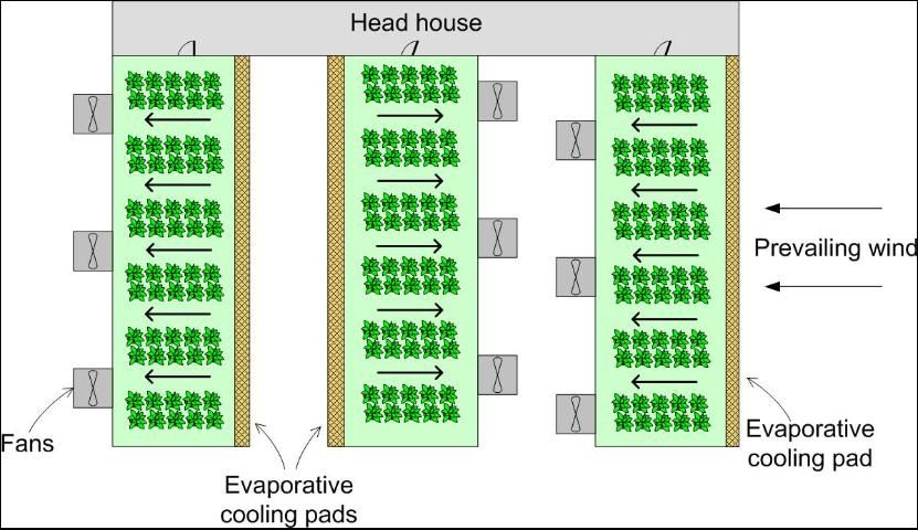
- When possible, locate pads on the prevailing summer wind side and locate the fans on the downwind side of the greenhouse. If the pads are sheltered by another greenhouse within 25 feet, the wind effect is negligible and can be ignored.
- If it is necessary to face fans into the prevailing winds, increase fan CFM capacity by 10 to 15%, correspondingly increase fan motor horsepower, and add shutters or back draft dampers.
- The exhaust fans should not discharge toward the pad of another greenhouse unless they are separated by at least 50 feet.
- When fans from two adjacent greenhouses exhaust into a common area, they should be offset from each other to prevent the air from one blowing directly against the other (Figure 7).
Credit: Erin G. Webb
5. The maximum practical distance in the greenhouse from pad to fan should never exceed 200 feet. Distances of 150 feet or fewer reduce the amount of temperature increase across the greenhouse. For most greenhouses, approximately one foot of pad height is required for every 20 feet of pad-to-fan distance.
6. In very long greenhouses, it is more efficient to locate pads at both ends with the exhaust fans at the center of the greenhouse using sidewall fans. Cooled air then flows from each end and is exhausted at the midpoint of the greenhouse. All fans should have automatic shutters to protect against inclement weather and prevent back drafts when not in use.
7. Fans should be properly screened and guarded to protect personnel from moving parts (fan blades, pulleys, and belts).
8. A correctly designed and installed pad system is essential to achieve maximum cooling performance. The evaporative pad must be a continuous section along the entire side or end of the greenhouse and must be the correct size and thickness. A space in the pad, such as a doorway, will create a hot spot through the greenhouse for a distance of 6 to 8 times the width of the blank space. Exhaust fans should not be spaced more than 20–30 feet apart (Figure 1).
Fan and Pad Cooling System Operation
Monitor the pad condition carefully. If you notice bare spots or thin areas in the pad, then much of the air entering the greenhouse is coming through these areas and creating hot spots in the greenhouse. To work efficiently, the pad, pump system, fan system, and control systems must be designed to operate as a unit. They must be checked frequently to ensure all parts are functioning properly. Doors of the greenhouse should be opened only when necessary to move people, plants, and equipment in and out. An open door can reduce the effectiveness of a pad cooling system significantly. A greenhouse with the best equipment and sophisticated controls can suffer without good management.
Controls
The evaporative pad cooling system must have adequate controls so the operator can adjust the greenhouse environment to provide adequate growing conditions for plants and a comfortable environment for workers. Thermostats are usually used to turn fans and pumps on and off as required to optimize response to outdoor climate changes and maintain more uniform greenhouse temperatures with lower operating costs. Thermostats should be checked each spring and fall against an accurate thermometer to ensure proper operation.
A humidistat can be used to control pumps and fans of the cooling pad system to help prevent excessive greenhouse humidity. However, humidistats are much less reliable than thermostats. If using a humidistat to control humidity is desirable, it is recommended that the humidistat be checked at least weekly to make sure that it stays in calibration. Humidistats should be checked against a psychrometer. Thermostats and humidistats must be located at plant level to function properly and should never be located on an outside wall.
Exhaust fans should be uniformly spaced not more than 20 to 30 feet apart. The fans may be wired so that the thermostats will turn on alternate banks of fans in sequence as the temperature demands. Some greenhouses are equipped with 2-speed fans, which should be controlled with 2-stage thermostats. During the time of year that a thermostat controls the heating system, the cooling thermostat should be set 5–10°F above the setting of the heating thermostat to avoid having the heating and cooling systems on at the same time.
A thermostat should be used as the main pump control. The thermostat should be set to stop the pump before all the fans go off so that the pad can dry out. If humidistats and thermostats control evaporative cooling water pumps, the humidistats should be wired in series with the thermostats. This will help maintain more uniform temperatures and avoid excessive humidities. It will also help conserve power and water.
Each thermostat and humidistat should have a manual control switch wired in parallel with it so that manual control can be used when desired. A safety disconnect switch should be located near each fan and pump. All controls and instruments, including thermostats, humidistats, and thermometers, should be shielded from the direct rays of the sun to avoid being influenced by solar radiation and to provide more accurate readings and control settings. Sensing elements should be mounted so that air can circulate freely around them. They should be located where they represent the average greenhouse conditions at plant level. Aspirating thermostats placed at plant level are the best choice. Do not locate thermostats near heating lines or air inlets or on outside walls. This will distort the readings from the desired environmental conditions for plants in the greenhouse.
Computers and Microcontrols
Thermostats and humidistats are reliable and inexpensive, but they are limited to simply turning pieces of equipment on or off in response to a change in temperature or relative humidity. Simple on-off controls cannot regulate environmental conditions exactly because they cannot sense how far the temperature or relative humidity is from the set point, or how rapidly the temperature or humidity is changing. Computers and microcontrollers can use software or hardwired circuits that incorporate logic to make decisions about the exact amount of heat or airflow required to produce desired environmental conditions.
Computers and microcontrollers are rapidly decreasing in cost while increasing in reliability and sophistication. They are now important tools that growers can use to improve crop quality and increase profits. Computer-based control systems can be linked to smartphone systems to allow operators to closely monitor greenhouse conditions from any location. Computer systems can also keep continuous records of greenhouse conditions and can be used to send messages or alarms to greenhouse operators when environmental conditions are out of range or when equipment fails. The increased control provided by these devices results in greenhouse conditions that provide a better environment for crop growth.