Unmanned aerial systems (UASs, UAVs, or drones) have emerged as an important tool for farmers, Extension agents, and landowners to map, monitor, and manage their properties. While commercial off-the-shelf (COTS) UASs have seen major improvements in usability, practical tradeoffs between platform configurations and sensor combinations are not always clear. This EDIS document provides an overview of the primary components of typical UASs to help growers, landowners, and/or Extension agents who want to configure and/or purchase a UAS or sensor system for agricultural operations. This document is one of a three-part series focusing on the applications, configuration, and best practices for using UASs in agricultural operations management.
Introduction
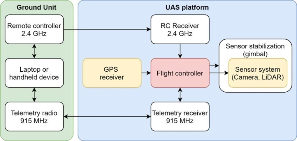
Any UAS needs a minimum set of components to be operable and to collect imaging and/or sensing data for agricultural or forest management uses. The main components include the airframe or flight platform, the propulsion system, the flight controller, a geographical positioning system (GPS), some combination of sensors, and other sets of systems that are useful for safe flight (such as landing or object avoidance sensors). While sensors and safety systems are in general configurable, the flight platform determines overall flight characteristics, and in combination with the flight controller, determines the flying experience and efficiency of UAS operations. Figure 1 shows a command-and-control schematic of a typical UAS platform. The sections below outline the main components and present an overview of the variations in most commercial off-the-shelf flight packages available as of December 2020.

Credit: Aditya Singh, UF/IFAS
Platform
This is the "body" of the aircraft that carries the flight controller, cameras and sensors, power supplies, propulsion mechanisms, and optional electronic components, such as GPS units. Platforms typically consist of one of the following:
- Multirotor platforms that take off and land vertically and derive propulsion directly from three or more vertically aligned propellers.
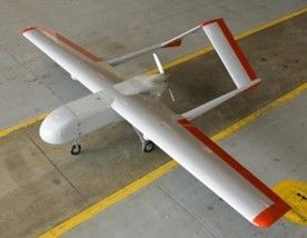
- Fixed-wing platforms that take off and land horizontally, and look and operate much like commercial aircraft, deriving lift from air driven by one or more propellers mounted horizontally along the axis of movement over conventional wings rigidly fixed to the fuselage.
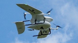
- Hybrid platforms that take off and land vertically using propellers mounted along the vertical axis but transition into horizontal flight by deriving lift from conventional wings once airborne.
Note that this is an extremely simplified list. Many combinations of flight modes exist that are available as commercial and/or experimental platforms. Table 1 compares advantages and disadvantages of flight platforms for typical users.
Power Supply
The choice of batteries or alternative power supply systems for any UAS platform is based on trade-offs in propulsion power demand, requirements of peripheral electronics or sensors, and payload capacities of the UAS. Power systems are therefore supplied as standard equipment with COTS UASs. It is generally a good idea not to switch batteries of different capacities or manufacturers and to stay within the payload capacities for which the UAS platform is designed. Increasingly, manufacturers are offering propulsion systems that are also "hybrid" in nature: these are typically configured as having a gas engine that provides the power source as well as LiPo (lithium polymer) batteries as emergency backups. These hybrid-powered UASs can lift heavier payloads (~10–15 lb) for longer periods (~1–3 hours).
In general, most UASs are powered by high power density rechargeable batteries. The most prevalent lithium polymer batteries (LiPo) are available in 3.7V cells internally connected in serial (denoted in "S" notation, i.e., 1S = 3.7V, 6S = 3.7 x 6 = 22V), and linked in parallel to produce a wide variety of capacities (amperage ratings). The amperage ratings on most LiPo batteries denote the length of time they can supply power at safe rates (in terms of current over time, mAh). Most batteries also have a "C" rating, which denotes the amount of peak current that can be discharged from a battery during peak power demand. In combination, a 6S –16,000mAh 25C battery can safely discharge 16A of current at 22V for an hour with a peak discharge capacity of 25 x 16 = 320A. LiPo batteries are popular for their power density and number of charge-discharge cycles, but they have considerable safety issues due to a propensity to catch fire (and explode) if stored improperly. Therefore, LiPO batteries are not allowed on commercial flights in checked luggage. They should always be stored, charged, and operated with utmost care according to manufacturer specifications.
Flight Controller
This is the "brain" of the UAS. The flight controller (FC) constitutes a microcomputer that gathers attitude, altitude, and heading information from on-board magnetometers (tilt sensors), accelerometers (G-force sensors), and geographical positioning systems (GPS), and calculates aircraft heading and position data in real time to provide inputs to motors that control how and where the aircraft flies. In most cases, the FC allows tablet, smartphone, or PC-based software to upload coordinates of flight paths (also called "waypoints") that guide the platform to execute user-defined flight patterns. Almost all major UAS manufacturers bundle aircraft with their versions of FCs. In addition, the open-source hardware community has developed its own FC for a variety of flight platforms (in addition to land-based rovers and watercraft). Details are available at https://www.dronecode.org/. For users in the process of purchasing UASs, it is important to check if the FC is open-source; if not, users should find out how many programmable "waypoints" can be programmed into flight plans, and whether sensors required for the particular application are supported by the flight controller. At the broadest level, the FC monitors flight information and allows the operation of sensors at locations that are defined by the user in the flight plan. In addition, the FC supplies the geolocation from the GPS to imagery and other data collected by the sensors.
Transmitter and Flight Radios
The flight controller is generally linked to a handheld transmitter (i.e., "remote control"), typically via a 2.4GHz radio connection that allows the manual control of the aircraft when flying. In addition, another radio operating at 915 MHz connects the base station (laptop computer- or cellphone-based application) with the flight controller on the UAS to exchange telemetry information (GPS location, speed, battery capacity, etc.) with the base station during operation.
Geographical Positioning System (GPS)
The GPS unit is essentially an on-board radio receiver operating at approximately 1.3GHz that receives real-time signals from a constellation of navigation satellites that orbit the Earth constantly. Almost all commercially available GPS units operate based on the collection of real-time positioning signals broadcast by orbiting satellites. Satellite signals are received, parsed, compared with satellite times and the geographical position of the sensor calculated in real-time, and relayed to the flight controller. GPS units require fixes from at least four satellites to estimate their location, with a larger number of fixes generally increasing the reliability of positional estimates. In this regard, GPS units that can utilize a larger array of constellations are generally considered more stable because they can switch between constellations to maintain heading and speed. In terms of accuracy, most inexpensive GPS units (~$50) can provide spatial positioning accuracies of 5–20 m depending on environmental conditions and satellite fixes. Users can take advantage of more recent technologies, such as real-time kinematic (RTK) or post-processed kinematic (PPK) GPS units, when higher accuracies (~2–5 cm) are needed.
RTK systems generally involve two separate GPS units, one located on the UAS (the "rover") and a second one at the base station (a fixed position near the UAS pilot). The two GPS units communicate in real time wherein the base unit relays the satellite carrier wave to the rover, and the rover calculates the difference in the carrier signals to determine the rover's position with centimeter-scale accuracy. A PPK system works similarly, but corrections are done after the flight (hence "post-processed"). PPK systems utilize algorithms to solve for positional inaccuracies by looking at pre- and post-flight locations to arrive at globally aligned solutions that can be applied to RTK-collected data to further refine location accuracy. However, RTK systems are expensive compared to single-GPS navigation systems (single station GPS: $50–$100; RTK system: $900–$1,200).
Sensor Systems
Sensor systems can cover a wide range of applications from simple video cameras to hyperspectral and thermal imaging payloads. Table 2 gives an overview of various sensor payloads and potential applications of each.
Other Critical Peripherals and/or Functions
When using most sensor systems and payloads, especially line-scanning instruments such as hyperspectral and/or LiDAR sensors, platform stabilization assumes a critical role in obtaining useful data. The vibration in the platform can cause problems that may be compounded due to error propagation through the sensor payload. It is generally recommended that the sensor systems be mounted on a gimbal-stabilized platform that is in turn also isolated from the flight platform using vibration dampeners. To ensure consistent data acquisition, a 3D gimbal that can stabilize the sensor payload in the yaw (left-right rotation), pitch (forward-backward tilt), and roll (side-to-side tilt) axes is recommended. Note that the gimbal is an actively stabilized platform and has power requirements that need to be considered.
In addition, there are various features that can be included in the flight platform to make UASs safer and more efficient to fly and operate. These might include: sense-and-avoid sensors that use ultrasonic waves to detect obstacles and help the FC carry out evasive action; propeller guards that help avoid damage to people or equipment by physically obstructing objects from falling within the propellers' rotational orbits; automated landing gear that can be retracted while flying to give the sensor suites unobstructed view of the targets; piezometric beepers and/or LED lights as auditory or visual warning signals; and programmable "fail-safes" that ensure the UAS does not fly outside of preset flight radii or altitudes.
Summary
This document is a broad primer for Extension agents and growers who are interested in utilizing emerging and increasingly available UAS technologies. While this document is not an exhaustive list of components (as of December 2020), it is intended as a broad summary of factors that should be kept in mind when purchasing a COTS UAS. Eventually, the combination of sensors, platforms, flight controllers, and peripherals will depend on the exact application context. Readers are encouraged to contact UF/IFAS remote sensing faculty to consult on specific needs.


