Introduction
Best Management Practices (BMPS) are practices which under a given set of conditions have the potential to enahnce water quality and quantity at a minimal cost. In the case of stormwater management, BMPs can be classified into two broad categories: structural and nonstructural controls and operation/maintenance procedures.
Nonstructural controls are those intended to improve stormwater quality by reducing the generation and accumulation of potential stormwater pollutants at or near their sources. Nonstructural controls are the first line of defense and include practices such as planning and management, wetlands and floodplain protection, education, proper fertilizer and pesticide application control and disposal, and "good housekeeping" techniques on construction sites. These practices are prevention oriented and are typically cost-effective.
Structural controls are those used to control stormwater volume and peak discharge rate, as well as to reduce the magnitude of pollutants in discharge waters through physical containment or flow restrictions designed to allow settling, filtration, percolation, chemical treatment, or biological uptake. These practices typically require considerable area, need proper long-term maintenance, and can be costly.
Generally, the more BMPs that are incorporated into the system, the better the performance of the treatment system. Although BMPs may have differing specific objectives, they often work together as part of a total system.
On-line BMPs temporarily store stormwater runoff before it is discharged to surface waters. These types of BMPs consist of systems that capture all of the runoff from a design storm. They primarily provide flood control benefits, with associated secondary water quality benefits. However, some on-line BMPS, such as wet detention systems, can do an excellent job of achieving both benefits (Figure 1). Off-line BMPs divert the first flush of polluted stormwater and isolate it from the remaining stormwater, which is managed for flood control. Off-line retention is one of the most effective water quality protection BMPs since the diverted first flush is not discharged to surface waters. Stored water is removed by infiltration, evaporation, and evapotranspiration.
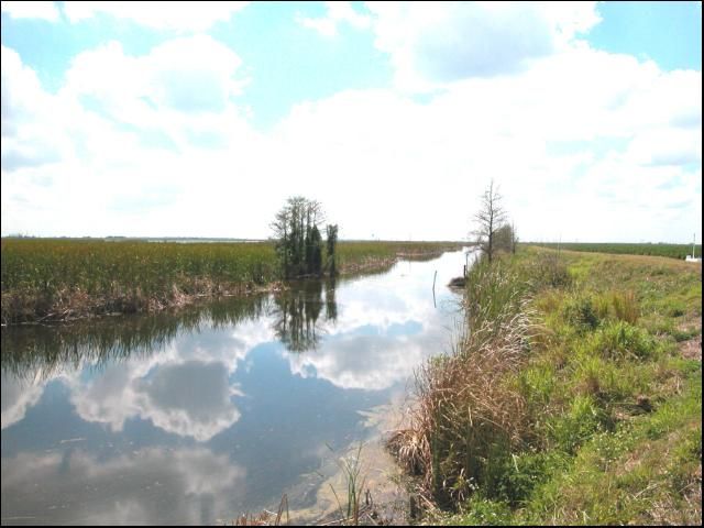
The requirements concerning surface water management for agricultural development as permitted by the Water Management Districts (WMDs) are outlined in Chapter 373 Part IV of the Florida Statutes and Chapter 40E-4 of the Florida Administrative Code. The WMDs have responsibility for the regulation of both quantity and quality of storm water within their jurisdictions by virtue of their authority under Chapter 373 F.S. They also have additional delegated responsibilities from the Florida Department of Environmental Protection (FDEP) for storm water quality. The WMDs, FDEP, and the United States Department of Agriculture (USDA) share jurisdiction over dredge and fill permitting for agricultural projects.
It is difficult to construct new agricultural projects in central and south Florida which do not have direct or indirect effects on the water resources of neighboring properties. The increased intensity of development and the need to use the more marginal and poorly drained lands make it difficult for agricultural developments to avoid impacts on adjoining properties. Regulation is seen as the means of attempting to maintain equity such that each owner gets the fair use of his land through the management of the water resource. Therefore, the basic review process by the WMDS is directed at maintaining a reasonable balance between new projects and existing land uses to protect Florida's water resources.
There are many factors involved in water management of citrus in Florida. However, since no two groves are the same, the optimum water management strategy for each grove must consider the specific conditions for that particular grove. Not only do the physical grove conditions differ from site to site, the management philosophies of each grove owner or production manager can also be significantly different. As a result, there is no unique and simple way to identify good water management practices applicable for each citrus grove in Florida. Therefore, all factors need to be evaluated in order to identify appropriate water management strategies for each particular site.
Definitions
Detention
The process of reducing off-site storm water discharge rates by temporarily holding the water in a storage basin and then releasing it slowly over a period of time is termed detention. The objective of a detention facility is to regulate the runoff from a given rainfall event and to control discharge rates to reduce the impact on downstream stormwater systems.
Detention basins typically have water quality enhancement benefits due to settling of suspended solids, adsorption of nutrients and some pesticides by soils, nutrient uptake into vegetation, and biological processes such as denitrification. In agricultural retention basins, stormwater runoff is tyically held on-site and then gradual release after the peak of the storm inflow has passed. Runoff is held for a short period of time and then slowly released off-site via a natural or constructed watercourse, usually at a rate no greater than the pre-development peak discharge rate.
Generally, detention facilities will not reduce the total volume of runoff, but will redistribute the rate of runoff over a period of time by providing temporary "live" storage of a given volume of stormwater. The volume of temporary "live" storage provided is the volume indicated by the area between the inflow and outflow hydrographs. A major benefit derived from properly designed and operated detention facilities is the reduction in downstream flooding. Other benefits include reduced costs for downstream stormwater conveyance facilities, reduction in nutrients and pesticides lost to receiving streams, and enhancement of natural wetland areas.
Retention
The prevention of stormwater runoff from being discharged into receiving waters by storing it in a storage area is termed retention. Water is retained stored until it is lost through percolation, removed by evapotransipation by plants, or through evaporation from the free water surface. Retention systems are designed to not have any off-site discharges.
A retention area is used to store runoff from a selected design storm or specified treatment volume. Retention areas reduce stormwater volume, peak discharge rate, off-site pollutant loading. They may also increace the recharge to shallow groundwater aquifers. The applicability of this practice is primarily dependent upon the ability of the soils to percolate stormwater runoff, and the availability of adequate land area for the retention site.
Geologic, topographic, and soil conditions must be considered in determining site suitability. Besides soil infiltration rates, the single most significant limiting factor in many cases is the availability of sufficient land area to provide the necessary storage volume. Current requlations require that soil and water table conditions must be such that the retention system can precolate and/or evaporate enough water to provide for a new volume of storage within a few days. When retention systems are vegetated (as recommended), stormwater runoff should percolate within 24-36 hours to assure viability of the vegetation.
Benefits of Retention/Detention
Expanding citrus acreage in south Florida has raised concerns regarding water quality degradation and effects of water table fluctuations on the hydrology and water table levels withing the affected watersheds. The primary water quality concerns are typically nutrients, sediments, and pesticides.
Interest has steadily increased over the last two decades in the use of natural (physical, biological, and chemical) aquatic processes for the treatment of polluted waters. This interest has been driven by growing recognition of the natural treatment functions performed by wetlands and aquatic plants, by the escalating costs of conventional treatment methods, and by a growing appreciation for the potential ancillary benefits provided by such systems. Aquatic treatment systems can be divided into natural wetlands, wet detention/retention systems, and aquatic plant systems. Of these methods, wet detention/retention systems have received the greatest attention for treatment of storm water pollution.
Wet detention/retention systems are not typically intended to replace all of the functions of natural wetlands, but serve to minimize point source and non-point source pollution prior to its entry into streams, natural wetlands, and other receiving waters. Wet detention/retention systems can provide many of the water quality improvement functions of natural wetlands with the advantage of control over location, design, and management to optimize those functions.
Wet detention/retention systems vary widely in their pollutant removal capabilities, but can effectively remove a number of contaminants with removal rates as high as 95 and 99% for some non-dissolved nutrients and pesticides, respectively. Some of the most important removal processes are purely physical processes such as sedimentation via reduced velocities and filtration by hydrophytic vegetation. These processes can produce excellent removal rates for suspended solids, particulate organic matter (particulate biochemical oxygen demand, known as BOD), and sediment-bound nutrients and metals. Oils and greases are removed through photo-degradation and microbial action. Similarly, some pathogens are also effectively removed in wet detention/retention systems via sedimentation and filtration, natural die-off, and UV degradation.
Dissolved constituents such as soluble organic matter, nitrogen and phosphorus tend to have lower removal rates. Soluble organic matter (such as dissolved organic nitrogen and phosphorus) is largely degraded by bacteria in the water column, plant-attached algal and bacterial associations, and microbes at the sediment surface. Nitrogen is removed largely through microbial action (such as denitrification), plant uptake, and volatilization. The microbial degradation processes are relatively slow, particularly the anaerobic steps, and require longer residence times, a factor which contributes to the more variable performance of wet detention/retention systems for these dissolved constituents.
Phosphorus is primarily removed through soil sorption processes that are slow and vary based on soil properties. Phosphorus is also removed through plant assimilation and subsequent burial in organic litter. Consequently, phosphorus removal rates are variable and typically lower than for nitrogen.
Metals are removed largely through adsorption and complexation with organic matter and other soil and water components. Removal rates for metals are variable, but are consistently high for lead, which is often associated with particulate matter.
Wet detention/retention systems that incorporate wetland plants can be expected to achieve or exceed the pollutant removal rates estimated for wet detention alone. Wet detention/retention systems are most effective as part of a BMP system.
Advantages: Properly constructed and maintained systems can effectively remove many pollutants from stormwater. Wet detention/retention systems can be used to reduce storm water runoff peak discharges as well as provide water quality benefits. Properly designed wet detention/retention systems can serve not only to control storm water volume and reduce pollution, but they can also provide wildlife habitat and aesthetic value. Wet detention/retention systems may also contribute to thermal moderation. This may be of importance to the grove during extreme cold periods.
Maintenance: Wet detention/retention systems have an establishment period during which they require regular inspection to monitor hydrologic conditions and ensure proper vegetative establishment. Long-term operation and maintenance, including maintenance of structures, monitoring of vegetation, and periodic removal of accumulated sediments, must be provided to ensure the successful function of the system. Frequent initial maintenance to remove opportunistic species is typically required if a diverse plant community is desired.
Grove Drainage Systems
In the poorly-drained sandy soils of the South Florida Flatwoods (soil series such as: Basinger, Immokalee, Myakka, Pineda, Riviera, Smyrna, Wabasso, Winder) control of the naturally high water table and rapid removal of excess surface water from rainfall are essential for citrus production. The surface water drainage system is typically designed to remove at least 4 inches per day from the grove. The drainage system generally includes beds, water furrows, lateral ditches, collector ditches, and may include perimeter ditches and discharge pumps.
To facilitate surface water management and provide additional root zone above the groundwater level, trees are generally planted on beds that are constructed between water furrows that are generally 48 to 55 ft apart. Water furrows are cut 2 to 3 ft deep and the soil is mounded between them to provide a 2½-3½ ft bed height from the bottom of the water furrow to the crown of the bed (Figure 2). The single row beds (typically 30 ft wide) in older groves are becoming increasingly rare as groves are replanted on 2-row beds. Wider multiple (4-6) row beds are sometimes seen, particularly in areas where shallow fractured limestone is encountered.
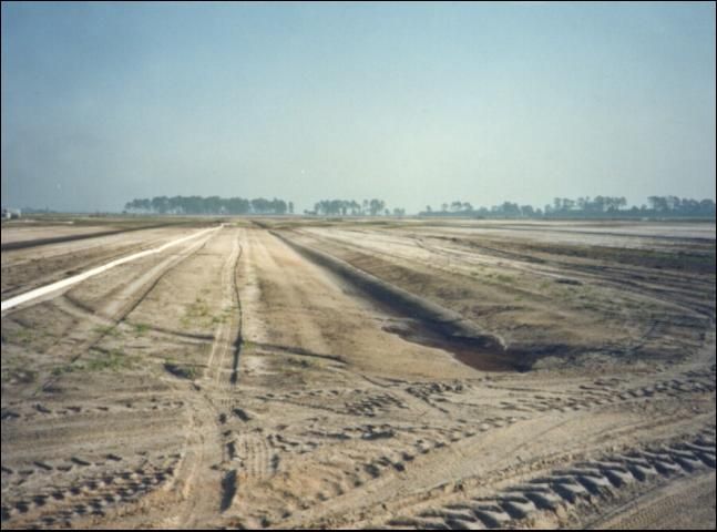
Lateral drainage ditches (Figure 3) are cut at right angles to the beds and water furrows and typically spaced no more than 1320 ft apart. Water furrows normally drain into the ditches via 6- to 8-inch flexible polyethylene or rigid PVC pipe. The pipe is installed in the bottom of the water furrow and sloped to discharge at approximately 1 ft above the bottom of the ditch. Ditch size varies depending upon the area served and water management district criteria. In general, lateral ditches have a 14-15 ft top width, 4 ft bottom width, 2:1 side slopes, and a depth of at about 5 ft.
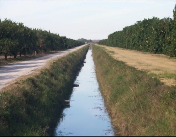
Drainage water from several lateral ditches usually is accumulated in collector ditches and conveyed off-site. Discharge may be by gravity if topographic relief allows, but discharge pumps are often required. The size of the collector ditches and related pumping facilities is dependent on factors such as size of the area being served, soils, bed and water furrow design, and slope of ditches.
In some soils (such as Myakka and Immokalee series) drain tiles are sometimes installed for additional control of the water table. The drains typically consist of perforated 4-inch diameter, flexible polyethylene pipe covered with a nylon fabric sock that is typically installed down the center of every other bed. The drain tubing is installed on a slope corresponding to the flow of the swales at depths averaging 3 ft to 4 ft, depending upon the location of spodic or clay horizons.
High water tables or natural drainage from adjacent undeveloped properties may result in subsurface flow towards a grove. In order to intercept and control the off-site water table and off-site surface flows, it is often necessary to construct a perimeter ditch and dike. Frequently the perimeter ditch can serve as a collector ditch. Pumps may be required in the perimeter ditches to intercept seepage water in order to maintain satisfactory water table depths in the developed grove (Figure 4).
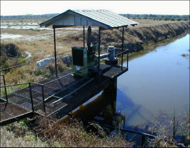
Permit Requirements
Each of Florida's Water Management District (Figure 5) issue Environmental Resource Permits (ERPs) and Water Use Permits (WUPs) to allocate water for reasonable beneficial uses and to protect the water resources of the state. Reasonable beneficial use is defined as the use of water in such quantity as is necessary for economic and efficient utilization for a purpose and in a manner which is both reasonable and consistent with the public interest. ERP permits address storm water management issues, and are generally issued for a period of 5 years. These permits are transferred to the operational phase once a project is constructed.
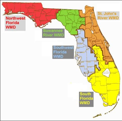
Water use permits are granted for fixed periods of time. The duration of WUPs may be up to 20 years. However, WUPs are generally issued for shorter durations due to a lack of information needed to commit water resources for longer periods of time. In order to use the water source, applicants must justify:
- The quantity of water requested
- The need, purpose, and value of the use
- The suitability of the source for its intended use.
The method and efficiency of use, water conservation measures, and the practicality of reuse or the use of lower quality water are also considerations.
Applicants must also show that the proposed use will not interfere with any exixting legal use of the water. The extent and amount of harm caused, whether that harm extends to other lands, and the practicality of mitigating harm by adjusting the quantity or method of use are also considered. Any adverse actions from using the water such as water quality degradation or increased risk of flood damage need to also be addressed in permit applications. In the case of groundwater withdrawals, extensive modeling (and sometimes testing) of the aquifers concerned is necessary to achieve this requirement.
The following issues must normally be addressed to receive an ERP permit for an agricultural project:
- Off-site discharge analysis and design, upstream/downstream
- Floodplain encroachment considerations
- On-site storage, quality/quantity
- Soils and vegetation review
- Low flows and water table maintenance considerations.
Surface Water Management
Because of the drastic changes in water table and drainage required for successful production of citrus on the Flatwoods, the main resource protection concerns center around effects on wetlands and water quality. In addition changes to surface water discharge rates must be addressed to meet criteria adopted by Florida's WMDs.
Increased Runoff Rates
Properly designed surface water management systems can minimize storm water runoff rates. Runoff rates are reduced by designing detention areas that are located between the grove area and the ultimate off-site discharge points. Typically these are diked off areas that receive inflow from the grove area via either gravity or pumped discharge. Outflow from the detention areas (often called reservoirs) occurs at discharge structures that are designed to restrict the flow rate to pre-development peak rates. This results in a build up of water levels in detention areas for a short period of time following major rainfall events.
Water Quality
Pollutant loadings in the form of sediments and dissolved agrichemicals can and should be minimized by the use of BMPs. In order to obtain an ERP from the appropriate WMD, grove developers must either agree to provide on-going monitoring of discharge water quality or design a system to meet the criteria for water quality treatment. In most cases, these criteria are achieved via detention areas. The detention areas provide attenuation of peak runoff rates and allow the drainage water to be released at lower rates over a longer period. Studies have also shown that detention areas are effective in providing water quality treatment and improved quality of stormwater runoff. Some WMDs accept alternative forms of water quality treatment auch as the use of grassed filter strips.
Impacts to Wetlands
The WMDs have a fairly clear legislative mandate to protect wetland resources. In addition, the USDA regulates direct impacts to wetlands via the discharge or deposition of fill for agricultural projects. Both agencies are also tasked with assessing and regulating secondary and cumulative impacts. It is therefore important to try to eliminate impacts to wetlands from proposed designs. The issues can be fairly complex to the extent that it usually becomes cost effective to retain consultants in the field to prepare designs and permit applications to address them.
Directing project discharges to off-site wetlands can counteract the effect of drawdown from adjacent citrus development. When this is done, it is important to try to maintain the pre-development delivery system. For example, if runoff traditionally was via sheet flow, then the project should discharge to a spreader swale to restore the runoff to sheet flow before it enters a wetland. Maintaining hydraulic head within the water table of an adjacent wetland can be achieved by locating a detention area between the citrus grove and the wetland.
Incorporating wetlands into natural flowways carrying off-site flows through a project can provide a habitat mix of wetlands and uplands and connections between off-site and on-site undeveloped areas. This may also accommodate some wildlife species that are sensitive to habitat fragmentation. However, this option should only be considered for hydraulically disconnected wetlands or under conditions where the flow will not harm the wetland function.
Project Considerations
Any new project must maintain the status quo with respect to impacts on adjacent lands. Essentially this requirement is a good neighbor policy which must be observed. For example, historical upstream flows should continue to be passed through the property and not be blocked. Downstream flows should continue to be similar in rate and quantity to pre-development conditions, and discharges should be in the same locations. In addition, downstream water quality should not be degraded. Floodplains should not be encroached, either by volume or flow interruption, without compensating construction. In addition, on-site environmental conditions must be preserved.
Soils and Vegetation
On a new agricultural project, it is usually worthwhile to initially review the site from the perspective of both the agronomist and environmentalist. In all probability, the soils and vegetation will clearly indicate certain areas which are not farmable due to excessive drainage requirements. These areas will usually coincide with wetland areas considered as viable and preservation candidates by environmental interests. Since on-site storage of water will probably be necessary in the final design, such areas can obviously serve dual purposes.
In general, larger areas of preservation are preferred over pockets of small areas. This is particularly true where it is doubtful that the small areas will survive with the drainage necessary to support grove areas developed around them.
Floodplain Encroachment
Floodplain encroachment must be considered for both storage reduction and flow interference. This means that not only must a volume between the water table and flood elevation be preserved, but a continuous flow cross-section must be maintained. A water storage or detention area may partially serve this purpose, but it also may be necessary for land outside diked and farmed areas to remain undeveloped. The design refinements and review concerns associated with this subject are very much related to the site location both with respect to topography and local development intensity (a small grove in the middle of a large non-agricultural holding is likely to create only minimal off-site impacts)
Off-site Discharge
Facilities are normally designed for the 25-year storm event. In most new grove developments, pre-constructed works do not exist. It is therefore necessary to calculate upstream flows generated by the design event and pass them through or around the proposed project. Any discharge added from the project that would add to the historic flow must be limited to not cause additional adverse downstream impacts. This delicate balancing act to make post-development impacts meet pre-development conditions is normally accomplished by matching pre- and post-development peak discharges. Occasionally, the duration of higher stages may also be a concern (such as when the discharge enters an environmentally sensitive area). Duration issues are typically more related to continuous high discharges rather than the absolute peak discharge rate.
Off-site discharge can be routed around or through a new project. In most cases it will not be economical to attempt to mix the project storage area with the upstream off-site flows as they enter the project site. The backwater effects of such designs may cause flooding of upstream lands where there were previously no flooding problems. Therefore, most upstream off-site discharges are routed around the project.
In areas where sheetflow of unknown direction predominates, the WMDs usually require that the base of farm dikes be kept away from property boundaries. The minimum distance is usually 50 feet, but may be more in some cases. The construction of conveyance facilities may or may not be necessary in this setback area.
In areas where pre-constructed drainage facilities exist (such as locations served by local 298 districts, county drainage systems, etc.), discharges greater than natural may be allowed if the secondary facilities can deliver the project discharge to the primary system. Often, the discharge rate is determined as a prorated amount based on the project area as related to the total basin area.
On-site Storage
In addition to drainage quantity management, on-site storage may be necessary for water quality management. The storage may serve an additional purpose of irrigation supply, but this is usually likely only for deeper storage areas. Typical above-ground storage areas usually go dry during winter months when irrigation water is most needed. Dikes (levees) for storage areas located close to property boundaries should be more substantial than interior ones so that neighboring properties are protected from the flood impacts associated with any dike failure.
Water Quality
The WMDs have adopted certain criteria which offer the presumption that off-site water quality discharges will be satisfactory. The use of wet detention systems as described in this document is an example of meeting such criteria. Ultimately, it is still a permittee's responsibility to meet water quality performance standards as required by state law, regardless of the system used.
Low Flows and Groundwater Maintenance
WMDs require that projects not alter water tables in such a way that would cause off-site problems. They also require that projects not control internal water levels deeper than 6 feet below ground level. In some areas, this requires internal step down contour structures.
WMD Project Review
The WMD engineering staff typically reviews projects for basic compliance with existing criteria and normal agricultural and engineering practices. Sizes and dimensions are normally reviewed. Structural adequacy is not reviewed, except for obvious errors and inadequacies. Certification of above-ground storage area dikes are normally required upon completion of construction and semi-annually thereafter. Specific items of review include:
- Discharge structures—usually weirs and culverts; reviewed for dimensions to meet hydraulic criteria; typical check includes weir width and elevation, control mechanism (V-notch bleeder device) size and elevation, culvert size and elevation.
- Exterior levees—location, sizes, and elevations to allow passage of offsite flows, containment of project water, floodplain encroachment, and design calculations for stability, wave runup, etc.
- Bypass and flow-through conveyance—location, elevation, hydraulic capacity, and interaction between project and adjacent lands.
- Floodplain encroachment—consideration of floodplain location and elevation, activity in area or basin, and project dimensions and elevations.
- Internal facilities such as pumps discharging into storage area.
- Environmental considerations—projects are reviewed from aerial photographs to determine the need for a site inspection.
Detention Design Example
Design Components
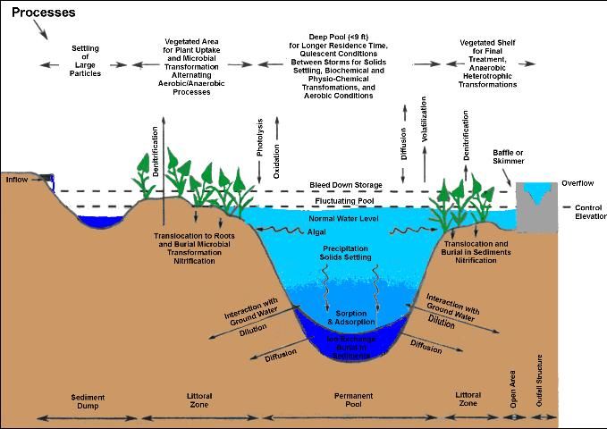
Wet detention ponds consist of a permanent water pool, an overlying zone in which the stormwater fluctuating volume temporarily increases the depth, and a shallow littoral zone to act as a biological filter (Figure 6). Extended detention times have long been recognized as a best management practice for treating urban runoff pollution, since longer detention times allow for increased sedimentation and biological processing. Some of the criteria generally used for detention system design are given in Table 1.
Permanent Pool
The most important feature of a wet-detention basin is the permanent pool. It allows for stormwater treatment between rain events before new stormwater displaces the treated water in the pond. Therefore, the size and the shape of the permanent pool should be one of the first considerations in any design. The design should provide for good circulation, mixing and residence time. This can be accomplished by creating maximum separation between the inflow and outflow, locating inflow inverts below the control elevation, using multi-cell ponds or flow baffles and eliminating dead areas.
For permanent pool storage volume, solids settling design curves usually assign more than 90 percent of the total pollutant removal to quiescent conditions between storms. The size of the permanent pool to watershed area should be 4 to 6 percent of the drainage basin to achieve this amount of pollutant removal. Residence time in the permanent pool must be balanced with the amount of time needed to enhance sedimentation and ensure adequate nutrient uptake without the risk of thermal stratification and the development of anaerobic conditions at the bottom of the resevoir. Two weeks is generally considered an optimal residence time. The depth of the permanent pool should be shallow enough to minimize the risk of thermal stratification, but deep enough to reduce algal blooms and prevent sediment resuspension.
Fluctuating Pool
The volume above the permanent pool that is slowly released within five days after a storm event is termed the fluctuating pool. This feature reduces peak flows downstream and provides some sediment and nutrient removal. This zone assures freeboard for closely spaced rain events which enhances mixing by providing additional time for mixing to occur. The bottom of the fluctuating pool, the lowest elevation at which water can be released through the outfall structure, is referred to as the control elevation. The control elevation should normally coincide with seasonal high water levels (SHWL).
Littoral Zone
The littoral zone is a shallow shelf around the perimeter of the pond or in some other configuration which promotes suitable conditions for plants to improve water quality by biological uptake and transformations. In turn, nutrient uptake in the littoral zone helps minimize the proliferation of free-floating algae by limiting the amount of nutrients available for phytoplankton. Some macrophytes have also been known to excrete chemicals that inhibit algal growth (which reduces competition for light and nutrients).
Outfall Weir
The outflow weir configuration controls discharges from the facility. A weir is an obstruction placed across the entire width of an open channel or conduit to interrupt flow and cause the water level upstream of the weir to rise until it flows over the top of the weir (Figure 7).
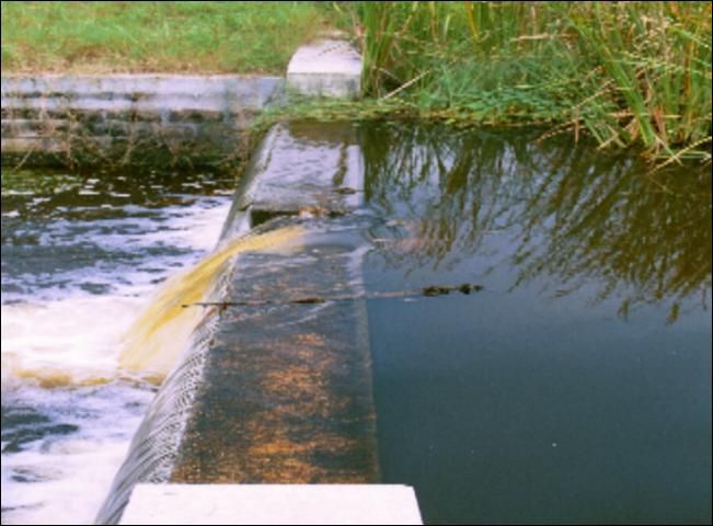
A weir that takes the form of a thin plate and is beveled on the downstream side of the upper surface so that a sharp upstream edge exists is called a sharp-crested weir. Equations that describe the flow over weirs are based on the flow over the weir taking the form of a nappe that freely flows clear over the downstream face of the weir. The flowing water should only contact the weir along the upper edge of the weir crest. At very low flows, the nappe often will not flow free of the weir face, and thus cannot be considered true weir flow.
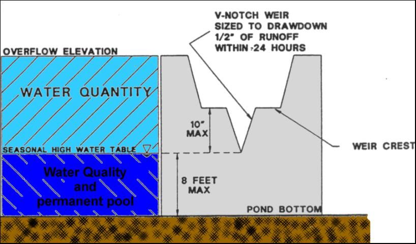
A sharp-crested weir may be equipped with a notch in the upper surface through which flow will pass. When this notch takes the form of the letter V, with the narrow point of the V pointing downward, the weir is called a V-notch weir (Figure 8).
The V-notch weir is used for measuring flow in channels or conduits that experience variable low flow rates because:
- At low flow rates, the nappe from a V-notch weir will flow clear of the weir face more readily than for other types of weirs.
- At low flow rates, the narrow opening near the bottom of the V-notch causes the water behind the weir to back up to a higher level than with a rectangular notch. As a result, the greater difference in water levels permits more accurate calculations of low-rate flows.
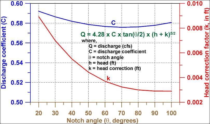
V-notch weir flow rates are typically calculated using the Kindsvater-Shen equation, which is presented in Figure 9 for Q in cubic feet per second (cfs) and water depth (head) above bottom of weir in feet. Head (h) should be measured at a distance of at least 4h upstream of the weir. It doesn't matter how thick the weir is except where water flows over the weir through the V. The weir should be between 0.03 and 0.08 inches thick in the V. If the bulk of the weir is thicker than 0.08 inch, the downstream edge of the V can be chamfered at an angle greater than 45° (60° is recommended) to achieve the desired thickness of the edges.
For accurate measurements, water should not cling to the downstream face of the weir. The water surface downstream of the weir should be at least 0.2 ft below the bottom of the V (dimension P in Figure 10) to allow for free-flowing fall of water. Measured head (h) should be greater than 0.2 ft due to potential measurement error at such small heads and the fact that the nappe may cling to the weir. The bottom of the V should be at least 1.5 ft above the bottom of the upstream channel and the average width of the approach channel (B) should be greater than 3 ft.

The equations were developed for h less than 1.25 ft and h/P less than 2.4 and for fully contracted V-notch weirs (a fully contracted weir has h/B less than or equal to 0.2). If a weir does not achieve some of the above criteria, it may be considered a partially contracted V-notch weir. Partially contracted weirs use a different graph for C which is a function of h/P and P/B. Fig. 9 does not account for partially contracted weirs, but for most practical purposes the difference in C is inconsequential.
Example
Calculate the discharge rate for a 90° V-notch weir with 8 inches of water flowing over the weir.
From Fig 9, C for a notch angle of 90° = 0.58 and k = 0.003.
h = 8 inches = 8/12 ft = 0.75 ft
tan (90°/2) = tan 45° = 1.0
Q = 4.28 x 0.58 x tan(90°/2) x (0.75 + 0.003)5/2
Q = 1.22 cfs x 448 gpm/cfs = 547 gpm
Construction Planning
Planning
Grove design should start with a thorough investigation of pre-development drainage patterns. Care must be taken to eliminate or minimize diversion of natural watersheds, particularly if they are feeding downstream off-site wetland systems. Off-site up gradient flows can be taken through projects via natural flow-ways or constructed channels. They may also be taken around projects in constructed ditches provided they discharge at their pre-development location. Most often off-site flows must be kept separate from project flows because mixing will require water quality treatment for the entire volume.
Avoiding direct impacts to wetlands can be achieved by setting back development lines to provide an upland buffer. This also eliminates the need to obtain a dredge and fill permit from the USDA. When setbacks are large enough, the indirect impact of water table drawdown can be minimized or eliminated. Another benefit is that the requirement for incorporation of upland buffers to accommodate wildlife in groves is realized. Some WMDs have developed technical procedures for determining the adequacy of development setbacks to eliminate the effect of drawdown on wetlands.
Incorporation of wetlands in detention areas may provide a mechanism to counteract the effect of drawdown. However, when detention areas are serving the function of attenuation of peak runoff rate, water levels will rise within them. The maximum safe depth for small impoundments is approximately 4 ft. This depth of water is too great to add to natural wetland systems for prolonged periods without seriously harming them. Therefore, it is necessary to analyze the results of an engineered storm routing and adjust the design, if necessary, to reduce the depth and or duration of excess inundation to avoid negative impacts.
A typical agricultural project is likely to be considered a minor impoundment, featuring a pumped discharge into one or more storage areas (which often are also preserved wetlands), with gravity discharge to an off-site receiving body and an overflow back into the property. A certain amount of soil storage is available at the beginning of most rainfall events. The storage becomes filled by infiltration, and no appreciable reuse of soil storage is assumed to occur during the storm. Likewise, once runoff reaches the open storage areas, the water stays there until it flows into the receiving body. Water levels in the storage areas will be equal to or lower than those elsewhere on the site. In a pumped system, one or both of these situations might not occur.
In the absence of a detailed dam structural safety analysis of above-ground dikes, the maximum above-grade water depth which can be stored is 4 feet. Freeboard should be no less than 2 feet more than the depth required for the design storm. Some project-specific factors that may affect these recommended criteria include: reservoir size, project configuration, and effects on neighboring properties if the system failed and the properties were flooded. All perimeter and storage area dike tops should be wide enough for typical operation and maintenance equipment.
The recommended style of overflow structure is either a non-adjustable riser with a weir crest attached to an outfall pipe which conducts flows back into the property; or a non-adjustable broad- or sharp-crested weir at a place in the dike where flow can go back onto the property. A simple outfall pipe with an invert at the proper elevation will not suffice because of anticipated erosion problems. The overflow structure at the weir crest should be at an elevation equal to that of the peak height of the routed design storm. The length of the weir should be such that the weir will return to the property the difference between the routed pumped inflow plus the 100-year 3-day rainfall on the reservoir minus the routed outflow through the control structure.
Construction Specifications
Initial retention or detention basin excavation should be carried to within 1 ft of the final elevation of the basin floor. Interior side slopes should be sodded immediately to prevent erosion and the introduction of additional sediments. Final excavation should be deferred until all contributing areas of the watershed have been stabilized. Light equipment should be used to remove accumulated sediments and achieve final grade without compacting the basin floor. After final grading, the basin floor should be scarified with rotary tillers, discs, or harrows to promote infiltration and grass establishment. Structural elements such as embankments, inlets, flumes, and emergency spillways, should be designed by a Florida registered professional engineer.
Construction Techniques
Proper subgrade preparation requires clearing and grubbing of land. Except for muck soils, the subgrade should be free of organic debris, demolition debris, and large stones and rocks. If no fill is required, the ground should then be smoothed and compacted. If the area requires fill, the surface should be scarified or roughened to facilitate bonding between the original soil and the fill. Do not place fill on a smooth compacted soil.
All fill material must be properly compacted. Large fill areas (such as embankments and building pads) can be mechanically compacted with heavy equipment in 6-8 inch lifts of compacted soil. Smaller above ground fills, such as berms, can be compacted with heavy and medium equipment, or with hand tampers. Backfilling around pipes and manholes is the most sensitive operation, particularly around the bottom half of a pipe.
Fill should be placed in 2–4 inch layer. Small rollers or tampers are commonly used. Compaction of fill can also be accomplished using time and/or water. Where time is not a pressing factor fill can simply be dumped in place and allowed to settle over a period of several months. The primary force causing settlement is rain. The process can be shortened to several days by constant inundation with a sprinkler. These techniques work best in very sandy soils. Regardless of the method used, a compaction test should be performed before permanent structures are constructed on top of fill material.
Design Alternatives
The following criteria provide acceptable alternative methods of achieving design pool and gravity discharge configuration when it is justified to provide all or part of the treatment volume below SHWL or control elevation, without design pool bleed down.
- Discharge devices below SHWL should be avoided
- Design pool volume below the control elevation to a depth of eight feet depth must be equal to one inch of runoff plus the calculated volume based on average residence time of 14 days and average total rainfall during the wet season (June through September)
- The minimum design pool volume below the control elevation to an 8 ft depth must be no less than 1.67 inches of runoff from the contributing area
- Systems discharging directly into Outstanding Florida Waters (OFW) should provide treatment and permanent wet pool volumes that are 50% greater than required for systems discharging to other receiving waters
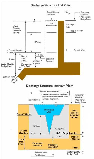
- The gravity overflow weir should be multi-stage, first having a V-notch or other equivalent drawdown control device sized to discharge 0.5 inch of detention runoff from the contributing area in 24 hours with 10 inches maximum head and then having a broad crested weir for higher discharges, including the 25 year, 24 hour event. The V-notch weir creates a minimum pond area and fluctuation to enhance surface aeration, circulation and mixing in the design pool.
- The control elevation (V-notch invert) should be above SHWL in the pond and above wet season tailwater in the receiving water, but no higher than two feet above SHWL.
- For gravity discharge systems with treatment volume below SHWL, credit for water quantity (discharge attenuation) storage may be allowed above control elevation and SHWL, if the V-notch is designed correctly.
- At least 35% of the pond bottom, based on area at control elevation, must extend below SHWL to help sustain the required littoral area; and the 35% littoral area should extend 2 ft maximum below the control elevation.
- Wet detention systems should be specifically designed to maximize circulation, mixing and residence time of inflow within the design pool by means such as: maximum separation of inflow and outflow points, locating inflow inverts below the control elevation, use of multi-cell ponds or flow baffles and other locally effective means to avoid dead storage areas.
Detention Pond Design
Example calculation for the volume of a wet detention design pool for a citrus grove.
Given: A 320 acre citrus grove project in South Florida using a Rational runoff coefficient of 0.30. The project discharge is to Class III waters from a wet detention system. Average wet season rainfall (June-Sept.) is 32.2 inches.
Step 1. Calculate treatment volume (Vp) as one inch of runoff over the entire 320 acres in the project.
Vp = Volume of water in 1 inch of runoff from project (ac-ft)
Vp = 320 acres x 1 inch x 1 ft/12 inches = 320 ac-in = 26.7 ac-ft
Step 2. Calculate the permanent wet pool volume to be retained below the control elevation to eight feet depth. It must be the greater of: a) the volume calculated to provide an average residence time of 14 days based on average total wet season rainfall of 32.2 inches; or, b) the volume produced by 0.667 inches of runoff from the contributing area.
Volume for 14-day residence time (VR)
VR = A x C x P x R x 0.083
Where,
A = Drainage area (ac)
C = Rational runoff coefficient (dimensionless). The Rational runoff coefficient is defined as the ratio of the peak runoff rate to the rainfall intensity. C depends on the infiltration rate, surface coover, channel and durface storage, and the intensity of rainfall. The value of C is typically set to about 0.30 for citrus developments, but may vary considerably for other land uses (Table 2).
P = Historic wet season average daily rainfall rate (June - September is 122 days)
R = Residence time (days)
0.083 = conversion factor from inches to feet (1/12)
for this example, A = 320 ac, C = 0.30, P = 32.2 inches, R = 14 days
VR = 320 ac x 0.30 x 32.2/122 x 14 x 0.083 = 29.4 ac-ft
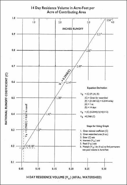
Vr can also be calculated using Figure 11, knowing the design area and Rational Coefficient.
In this example, find C = 0.3 on the vertical axis and move right until the diagonal line is intersected. Read the value of about 0.09 on the VB axis. Multiply the VB axis value by A (drainage acres) to find the permanent wet pool volume (in ac-ft). VR by this method = 0.09 x 320 = 28.8 acres, or slightly less than the value of 29.4 ac-ft calculated above.
Based on 0.667 inches of runoff
Vmin = 320 ac x 0.667 in x 1ft/12 in = 17.8 ac-ft
Since VR is greater than Vmin, the permanent wet pool volume (VB) = 29.4 ac-ft (the value of VR)
The design pool volume (VD) will be equal to the treatment volume (Q) plus the permanent wet pool volume VB
VD = Q + VR = 26.7 + 29.4 = 56.1 ac-ft
Step 3. Calculate the average minimum pond area (AS).
Based on the treatment volume below the control elevation of V-notch weir, 1/2 inch of runoff, and 10 inch maximum head based on design pool volume at maximum depth.
Vw = 320 ac x 0.5 inch 1 ft/12 in = 13.3 ac-ft
AS = 13.3 ac-ft / (10 inch x 1 ft/12 inches) = 16.0 ac
Based on design pool volume, which equals:
Vp (26.7) + VB (29.4) = 56.1 ac-ft
Using criteria 2 and 8 of Design Alternatives section (Page 11),
56.1 ac-ft = (0.35 x 2 ft x AS) + (0.65 x 8 ft x AS)
AS = 56.1 / 5.9 = 9.5 ac
Check max head (H) = Vw/AS = 13.3 / 9.5 = 1.4 ft = 16.8 inches
Since 16.8 inches is greater than the maximum allowable of 10 inches, the minimum pond area would be based on AS and cover 16.0 ac.
Outfall Structure
The basic criteria for detention is to store the first inch of runoff (or the runoff from a 2.5 inch rainfall, whichever is greater). The first inch must be detained and allowed to release over a 5-day period. This means that if the release is by gravity, the discharge structure would be designed to discharge about 1/2 inch the first day. As the upstream head declined, subsequent day releases would decline and the remainder of the detained water would get out in about 5 days.
Internal canals, ditches, swales, etc. are often desired to be used to meet detention criteria. However, this is usually impractical. Normally, detention in grove ditches is not compatible with on-farm flood protection. In addition, calculations are based on average wet season water table elevations. Therefore, detention in grove ditches under such circumstances usually causes a significant decrease in protection and an increase in risk of water damage to trees.
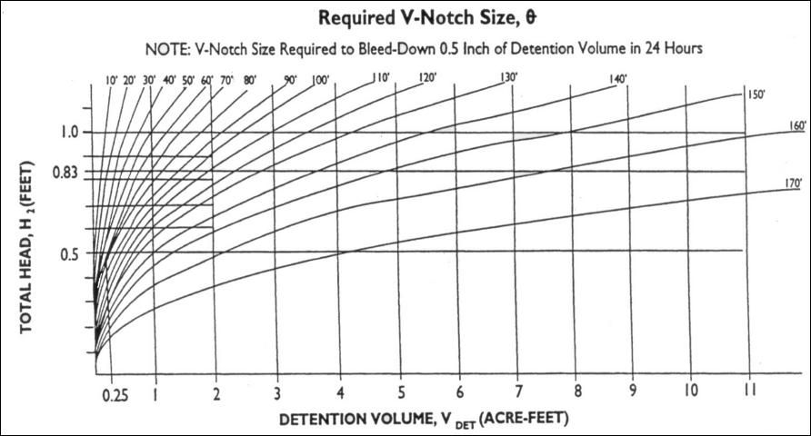
The typical discharge structure is a V-notch weir that is designed to pass the design storm through the V, but allows emergency discharges over the top of the structure in extreme rainfall events (Figure 12). The size of the V-notch weir can be calculated using Figure 13 for typical detention systems.
Example:
Calculate the size of V-notch weir required to bleed down 0.5 inches of water in the first 24 hours for a detained volume of 5 ac-ft if the maximum depth of water above the V is specified as 10 inches.
H = 10 inches/(12 in/ft) = 0.83 ft
Enter Fig. 12 on the vertical axis at H = 0.83 and move to the right until the Vdet = 5.0 ac-ft line is intersected. Read the V-notch size from the graph as about 150°. The design outfall structure would have a V-notch weir with a 150° notch angle.