Introduction
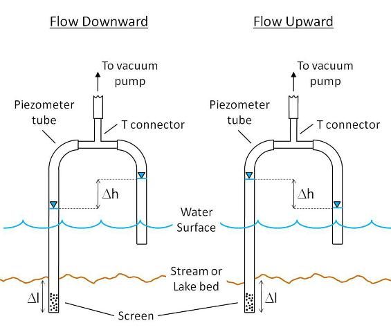
Mini-piezometers are simple instruments for measuring the direction of water flow between groundwater and a surface water body such as a lake or stream (Figure 1). Often temporarily installed, mini-piezometers are essentially scaled-down versions of piezometers, which are routinely used to make groundwater level measurements. When combined with surface water level measurements they can be used to determine the direction of water flow. Mini-piezometers are particularly useful in situations where many measurements are required, cost is a concern, or access to field sites is limited. While mini-piezometers can be purchased commercially, they are easily built using components readily available from hardware and autoparts stores. This document is intended to aid those who are engaged in surface water—groundwater exchange studies in cost-effective construction, installation and use of mini-piezometers.
Materials and Tools Required
Materials
- 1/2 inch outside diameter (OD) PVC or steel pipe outer casing (or similar diameter)
- Disposable drive point or cap to fit on end of outer casing (described below)
- 3.8 inch (OD), 1/4 inch inside diameter (ID) or similar clear flexible tubing (vinyl, polyethylene or tygon)
- "T" connector to fit clear tubing
- Filter fabric (to cover screen)
- Small wire-ties
Tools
- Rubber mallet or sledge hammer and hammer-cap
- Vice grips (optional)
- Hand vacuum pump
- Small Reservoir (~ 8–16 oz) to connect to hand vacuum pump (optional)
- Tape measure or ruler
- Utility knife
Construction
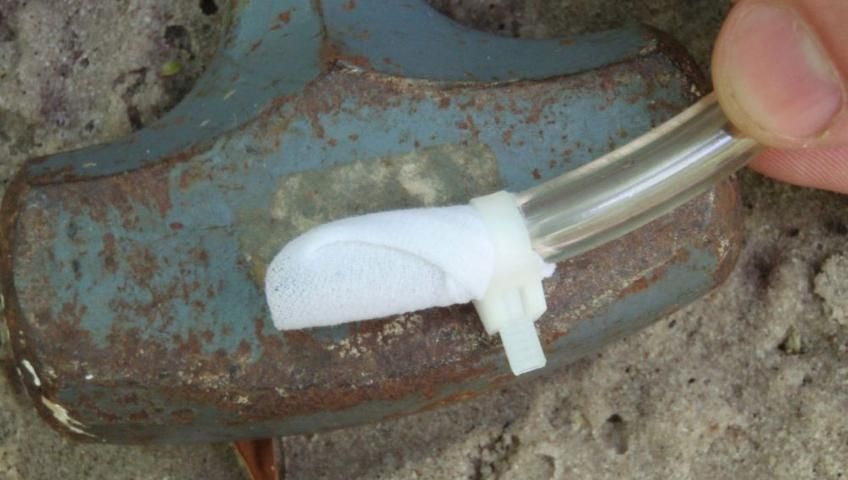
Cut a 5-6 foot length of clear tubing and cut small holes or slots along 1–2 inches of one end using the utility knife (lengths of tubing, screening, and casing mentioned here may vary depending on field conditions). This will be the 'screen' of the mini-piezometer shown in Figure 1. Wrap the screen with the filter fabric and secure to the tube using a wire-tie. The filter fabric will prevent clogging of the screen by fine sediment. A section of nylon stocking works well as the filter fabric (Figure 2). Cut any excess length from the wire-tie so it will pass through the outer casing during installation. Next, cut a 3–4 foot length of clear tubing, this section will be used to measure the surface water level (Figure 1). Attach both tubes to opposite ends of the crossbar of the T connector. Cut a 1 foot length of clear tubing and connect to the top of the T connector. Set aside.
The type of sediments of the stream or lake bottom will dictate the best material to use for the outer casing of the mini-piezometer. In coarse, sandy sediments a length of schedule 40 PVC pipe may be adequate. In finer, compacted sediments steel pipe will be better suited. In sediments that are extremely difficult to penetrate, the cap can be constructed in a conical shape to make driving the casing into the sediment easier.
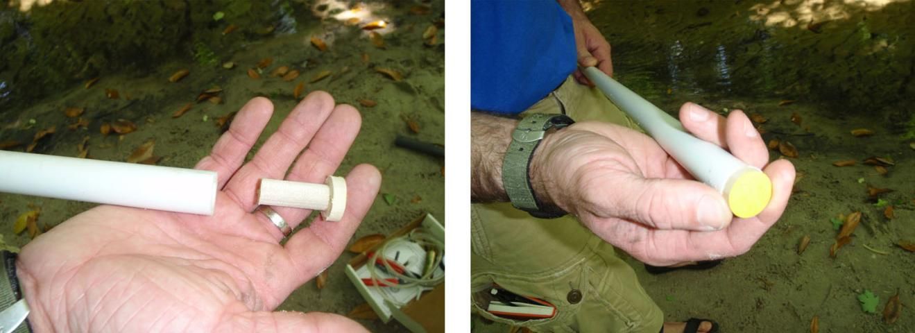
To prepare the mini-piezometer for installation, first place the disposable drive point or cap on one end of the outer casing (Figure 3). The drive point should be made of biodegradable and environmentally benign material since it will be left in the stream or lake bed after installation. Some researchers have recommended using metal carriage or lag bolts for this purpose. These are not recommended. A better alternative can be easily constructed from two untreated wood dowels, one of 1/2 inch diameter and the other of 3/4 inch diameter. A 1/4 inch slice of the larger dowel can be glued with wood glue to a 1-inch length of the narrower dowel to create a cap that will decompose naturally when left behind in the stream or lake bed (Figure 3).
Installation
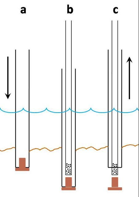
To install the mini-piezometer, drive the outer casing, with cap in place, into the sediment to the desired depth (Figure 4a). Deeper depths typically produce more reliable results but shallower depths may be desired depending on the purpose of the mini-piezometer. Multiple mini-piezometers can be installed at different depths in the same location, depending on the objective of the study. If PVC pipe is used as the outer casing then it may be driven into the sediment using a rubber mallet. If metal pipe is used, and the sediment is difficult to penetrate, then a sledge hammer and hammer cap placed over the outer casing may be used.
Once the outer casing is at the desired depth, thread the clear tubing, screen-end first, down to the bottom of the outer casing (Figure 4b). Remove the tube from the T connector so the casing can be removed. Next, remove the outer casing from the sediment, taking care to hold the tube in place as the casing is removed (Figure 4c). If a metal casing is used, vice grips can be used to pull the casing from the sediment using a twisting motion. Once the outer casing is removed, reconnect the tube to the T connector (Figure 1).
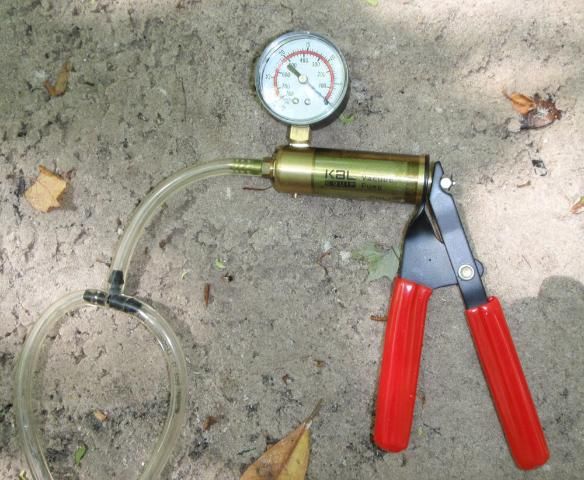
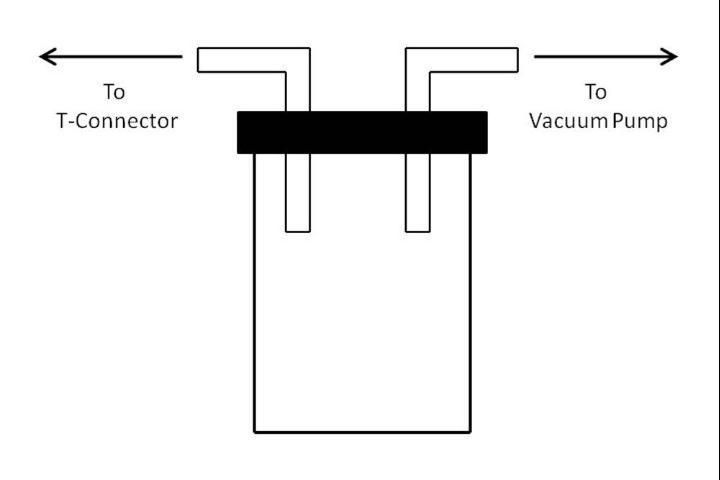
Once installed, the mini-piezometer must be 'developed'. Development ensures that the screened section of the mini-piezometer is in direct contact with groundwater in the surrounding sediment. Development can be done by drawing water out of the mini-piezometer using a hand-held vacuum pump (Figure 5). Hand-held vacuum pumps are available from local autoparts stores where they are sold as part of a kit for bleeding automobile brake lines. When using a vacuum pump to draw water out of a mini-piezometer, a reservoir can be used to prevent water from entering the vacuum pump (Figure 6). Alternatively, a longer length of clear tubing connected to the vacuum pump can be used. Following development, the water level in the mini-piezometer must be allowed to come back to its natural level, or equilibrate. Equilibration can take as little as a few seconds in coarse textured soils but could take minutes or hours in less conductive, finer soils. Successive measurements of water levels can be used to determine when the water level has come to equilibrium.
Measuring the Direction of Flow Using the Mini-piezometer
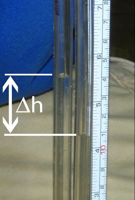
To measure the direction of water flow between groundwater and surface water, submerge the surface water tube, being sure to keep it above the stream or lake bottom (Figure 1). If the groundwater level in the mini-piezometer is above the surface water level then the difference in water levels, or the difference in 'hydraulic head' (Δh in Figure 1) can be determined by simply measuring the height of water in the mini-piezometer tube above the stream or lake water surface. However, more accurate measurements can be made by attaching the hand vacuum pump to the short tube attached to the top of the T connector and applying a vacuum to draw the water levels up both tubes. Draw the water levels up the tubes until the two tubes can be placed side-by-side and the difference in water levels can easily be measured with a tape measure (Figure 7). In situations where the groundwater level is below the water surface of the stream or lake, measurements of the difference in hydraulic head may be difficult. In this case, using the vacuum pump to draw the water levels up will be much more convenient (and will result in more accurate measurements) to measure the difference in hydraulic head.
The difference in hydraulic head, along with the distance across it is measured (Δl in Figure 1) can be used to determine what is called the 'hydraulic gradient':

The hydraulic gradient is useful when mini-piezometers are used as part of a study to determine the 'hydraulic conductivity' of the stream or lake bed sediment. The hydraulic conductivity is a measure of the ease that the sediment can transmit a fluid (water). Mini-piezometers can be used themselves to determine the hydraulic conductivity of the sediment (when the ratio of the length of the perforated screen to the inside radius of the mini-piezometer tube is greater than 8, see: Baxter et al. (2003) in the list of references) or complimentary instruments that are specifically designed to measure the rate of flow between surface and groundwater can be used (such as seepage meters, see: Lee and Cherry (1978), Sanders (1998), and Rosenberry (2008) in the list of references for more information).
Some Final Remarks
There are several variants of mini-piezometers, all are functionally the same but slightly different set-ups may be more desirable depending on the situation in the field (see references for different variants of mini-piezometers). For example, solid PVC pipe can be used in place of the flexible tubing for more long-term installation in the stream or lake bed. However, in such cases it will be important to know the depth of the mini-piezometer screen since it may change with the movement of stream bed sediments. Also, the surface water tube can be placed in a stilling well (simply a section of slotted pipe securely anchored) in situations where flow is highly turbulent and it is difficult to get accurate measurements of the surface water level. Multiple mini-piezometers can be deployed for studies of spatial differences in hyporheic exchange of stream water. Due to their simplicity and low cost, mini-piezometers can also be useful for educational field demonstrations in the environmental sciences.
References
Baxter, C., Hauer, F.R., and W.W. Woessener. 2003. Measuring groundwater-stream water exchange: New techniques for installing minipiezometers and estimating hydraulic conductivity. Transactions of the American Fisheries Society 132: 493-502.
Lee, D.R. and J.A. Cherry. 1978. A field exercise on groundwater flow using seepage meters and mini-piezometers. Journal of Geological Education 27: 6-10.
Rosenberry, D.O. 2008. A seepage meter designed for use in flowing water. Journal of Hydrology 359: 118-130.
Sanders, L.L. 1998. A Manual of Field Hydrogeology. Prentice Hall, Upper Saddle River, NJ.
Winter, T.C., LaBaugh, J.W., and D.O. Rosenberry. 1988. The design and use of a hydraulic potentiomanometer for direct measurement of differences in hydraulic head between groundwater and surface water. Limnological Oceanography 33(5): 1209-1214.