Abstract
The use of unmanned aerial systems (UASs) for agricultural management has increased exponentially over the past decade. Applications of UASs include mapping and inventorying farmland and forested properties, scouting for nutritional deficiencies and disease incidence, and in the event of natural disasters such as hurricanes, performing damage assessments to assist insurance claims. Laws established by the Federal Aviation Administration regulate any use and operation of UASs and require operators to always be in possession of a valid Remote Pilot Certificate. For UF/IFAS Extension personnel, and likely many other universities and federally or state-funded institutions, recommendations for operating UASs may be adjusted per guidance from federal and state authorities. Recent guidelines from UF restrict the purchase of UASs from certain manufacturers due to changes in federal recommendations.
All UASs need periodic maintenance and repair. These changes have raised questions among Extension agents regarding which UASs to purchase and use, and how these changes affect their operations going forward. Free and open-source (FOSS) options may be a very useful alternative to commercial-off-the-shelf (COTS) UASs in the following ways.
- UASs using open-source guidance and control software are more flexible than COTS counterparts in terms of the number of supported sensors and flexibility in flight mission capabilities.
- FOSS UASs can be much cheaper to own, operate, and maintain.
- FOSS UASs have an extensive backing of developers that are generally helpful in solving a range of issues (e.g., flight planning, customizing airframes or sensors, and even post-mission data processing).
- While open-source systems have a somewhat steeper learning curve than most COTS systems, they encourage technical capacity building in teams that can add to human capital and enhance critical technical skills that are useful in almost all facets of agricultural technology management.
This publication provides guidance to help Extension agents and other UAS users get started with the ArduPilot Mission Planner (MP) software. MP is the most widely used, best supported, and stable open-source flight planning software deployed in tandem with open-source flight controllers such as the PX4 (https://px4.io/) and PixHawk (https://pixhawk.org/). The focus of this publication is to familiarize users with the features of MP and to provide a step-by-step guide to setting up and operating UASs using FOSS software.
Terminology
Introduction
ArduPilot is a full-featured, open-source autopilot software with support for fully autonomous UAVs, ranging from FPV racing, aerial photography, rovers, and even submarines. ArduPilot has many features and users, and is a well-supported FOSS platform. ArduPilot enables the remote control of multiple autonomous systems with compatible ground station software (ArduPilot Dev Team 2021a). In particular, the ArduCopter platform, a part of the ArduPilot software ecosystem, fully supports multi-rotor platforms (e.g., quad-, hexa-, and octocopters) as well as VTOL aerial platforms. Note that in common parlance, ArduPilot is the umbrella term for the firmware installed on flight controllers to allow autonomous control, but is often also spoken of in combination with Mission Planner (MP), which is the ground control counterpart. MP was created by Michael Oborne (ArduPilot Dev Team 2021b) to help create autonomous missions with simple point-and-click entries on Google MapsTM (or other third-party)-supported maps. MP is also capable of simulating missions to predict the behavior of a running vehicle without risking a physical drone.
Installation
Mission Planner requires a computer running Windows or Linux with Mono, but this guide will assume a user is running Windows. To install Mission Planner, download the installer file from https://ardupilot.org/planner/docs/mission-planner-installation.html. If the link does not work, the installer can be found at https://ardupilot.org. Upon installation, you may be asked to enable Altitude Angel airspace management data—this can be safely ignored. At this point, the program and all the necessary files should be present and ready to explore. For the purposes of this guide, the visuals and processes are gathered from version 1.3.75 build 1.3.7883.26333 of Mission Planner.
Graphical User Interface (GUI)
The Mission Planner GUI exposes the entire functionality of the platform, and as such, can come across as complicated at first glance. For the purposes of simple mission planning, however, the tools are easy to find. The program presents five main pages (Figure 1) that can be accessed from the navigation bar in the top-left corner, starting with “Data” and ending with “Help.” All relevant information is presented under the metric system.

Credit: J. Chintanadilok, UF Department of Computer Science and Engineering
Data Page
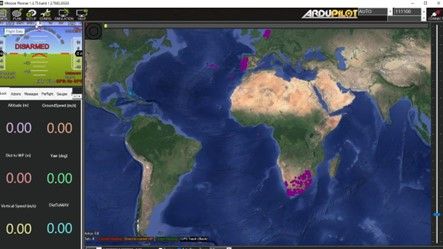
The landing page is the “Data” page (Figure 2) where a live stream of the telemetry and location from the UAS can be found. The dropdown menu at the top-right corner allows the user to establish a connection with the UAS. The HUD in the top-left region visualizes the current status of the UAV as a typical airplane. A quick access toolbar under the HUD allows the setting of quick actions (e.g., start mission, return to launch, etc.), data log viewing, gauge inspection, sensor readouts and statuses, servo controls (for manually triggering sensors and cameras if configured), and extra telemetry (additional information reported from the drone).
Credit: J. Chintanadilok, UF Department of Computer Science and Engineering
Plan Page
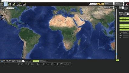
The “Plan” page (Figure 3) contains the core mission planning tools. Tools on this page allow the creation of missions of any complexity. Users generally spend the most time on this page for mission planning purposes.
Credit: J. Chintanadilok, UF Department of Computer Science and Engineering
Setup Page
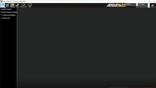
The “Setup” page (Figure 4) enables the setting of key features such as firmware, configurations for radios, gimbals, and other optional add-on hardware such as landing gear and laser altimeters for the UAV. Once set, these settings are not likely to be revisited.
Credit: J. Chintanadilok, UF Department of Computer Science and Engineering
Config Page
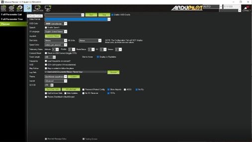
The “Config” (configuration) page (Figure 5) allows the specification of extra settings for MavLink configuration and UAV tuning parameters. Most of these settings can be modified using presets that can be imported or loaded in from the provided list.
Credit: J. Chintanadilok, UF Department of Computer Science and Engineering
Simulation Page
The “Simulation” page (Figure 6) contains the tools to simulate the flight plan in order to validate and adjust the flight plan as needed. This page allows the selection of the type of UAV (most commonly fixed-wing UAVs or multi-rotors) and shows a simulation of what the flight would look like in approximately real-life conditions.
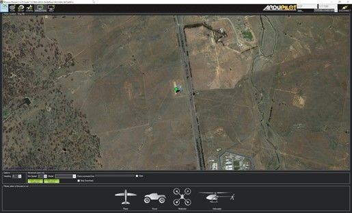
Credit: J. Chintanadilok, UF Department of Computer Science and Engineering
Help Page
The “Help” page (Figure 7) contains links for support documentation for the software and firmware, as well as efficient shortcuts to navigate MP. This page also includes buttons to check for software updates.
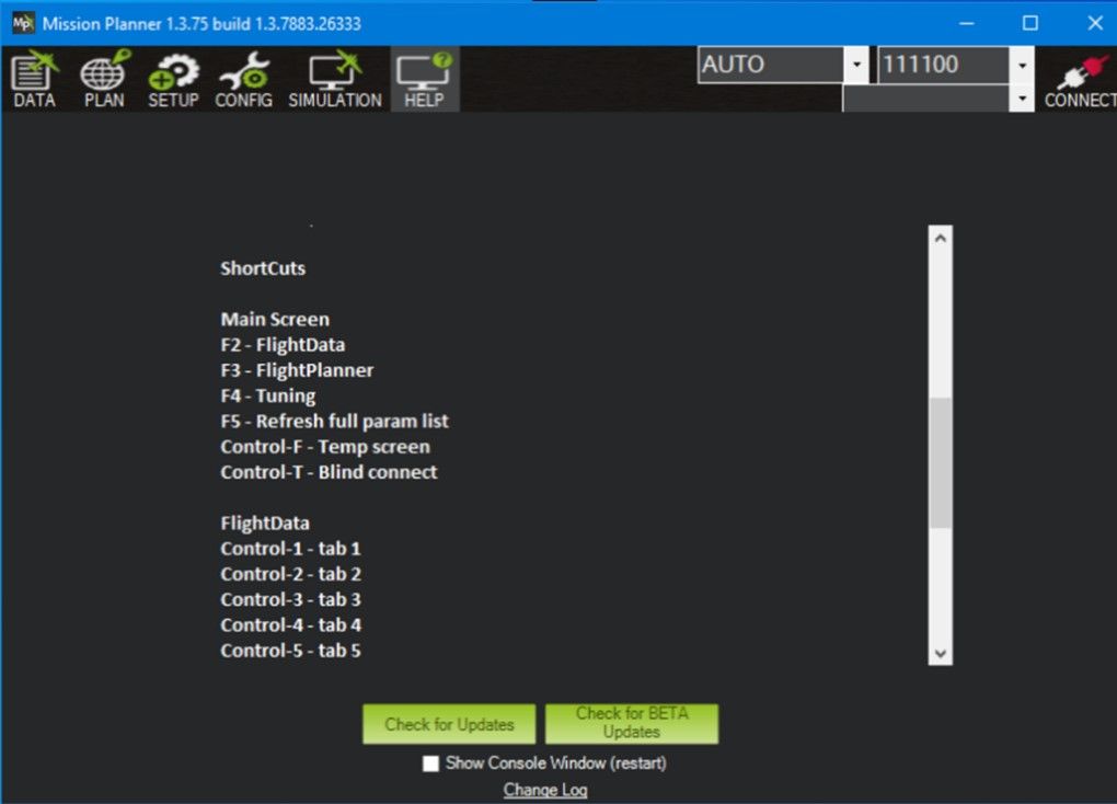
Credit: J. Chintanadilok, UF Department of Computer Science and Engineering.
Setting a Flight Plan for a Simple Survey
This section serves as a guide to set up a simple UAS flight plan with the most commonly used flight plan: a grid. Note that there are many other features, but the focus of this publication is to get a typical user started with planning a simple gridded survey using the “Survey (Grid)” tool. We assume the user is equipped with a laptop computer running Windows 8, 10, or 11, or Linux to minimize equipment needed (e.g., tablets, etc.).
- Switch on the UAS and wait until the initializing tune finishes beeping. Once done, plug the telemetry radio in any USB port on the computer being used as the ground station.
- Connect to your UAS with MP by clicking on the “Connect” button at the top right of the Data page. If this is the first time, MP might take some time to find the correct port to listen to the telemetry radio. One quick workaround is to open the device manager on the computer and look for any new USB connections when plugging in the telemetry radio. The baud rate is generally set at 57600.
- Once the telemetry radio is connected, the landing page (“Data”) will start showing the current status of the UAS. Click on the “Plan” page to move to the mission planning data entry page.
- On the “Plan” page, you will see the GPS location of your drone. Right-click on the drone and click “Takeoff” in order to set the takeoff location. Then, click and drag the map to navigate to the geographical region where you intend to set the flight path.
- Next, create a polygon of the area you wish to survey. To create a polygon, right-click on the map and select “Polygon | Draw a Polygon” in the context menu (Figure 8). Add “waypoints” by clicking on the screen (Figure 9). Double-clicking on the map finishes the current polygon.
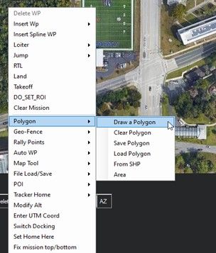
Credit: J. Chintanadilok, UF Department of Computer Science and Engineering
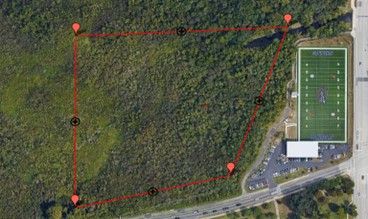
Credit: J. Chintanadilok, UF Department of Computer Science and Engineering
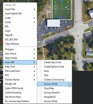
6. Once the flight polygon has been set, select “Auto WP | Survey (Grid)” (Figure 10). Note that there might be multiple Survey modes. The first one is the simplest and supports creating an area from a polygon and specification of the sensor configuration, if required. Survey (Gridv2) enables more granularity in the flight path generation process, but many of these features are not necessary for the purposes of remote sensing. Other survey features such as Wp Circle create a flight path on the perimeter of the boundary polygon. Additional information about the distinct Auto WP features can be found on the Mission Planner knowledge base.
Credit: J. Chintanadilok, UF Department of Computer Science and Engineering
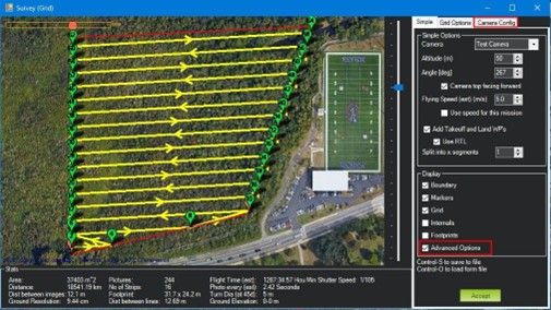
7. MP will provide a default mission layout across the grid. Select your sensor and specify the flight altitude and flight speed to see changes in the mission grid. If your camera or sensor is not already available in the dropdown menu, select “Advanced Options” in the Display box. Two tabs will appear: “Grid Options” and “Camera Config” (Figure 11).
Credit: J. Chintanadilok, UF Department of Computer Science and Engineering
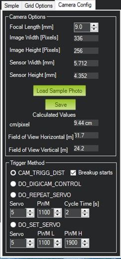
8. In the “Camera Config” tab (Figure 12), fill out your camera settings per manufacturer specifications. Alternatively, the “Load Sample Photo” button allows reading of the EXIF data (camera information embedded in the image file) from an existing photo from any sensor to automatically fill out most of the information. The Trigger Method specifies capture mode for the camera (i.e., how the controller tells the camera to take a picture). These settings are dependent on the sensor; more information can be found in the “Cameras and Gimbals” section of the ArduPilot documentation for most-used sensors. Note: Configuring the camera settings is essential to avoid blank regions. Blank spots can be caused if the spacing between flight lines is too wide. It is essential to avoid this because missing data could create added complexity in map stitching. Changes made to the sensor information will adjust the flight plan accordingly to ensure a complete data set.
Credit: J. Chintanadilok, UF Department of Computer Science and Engineering
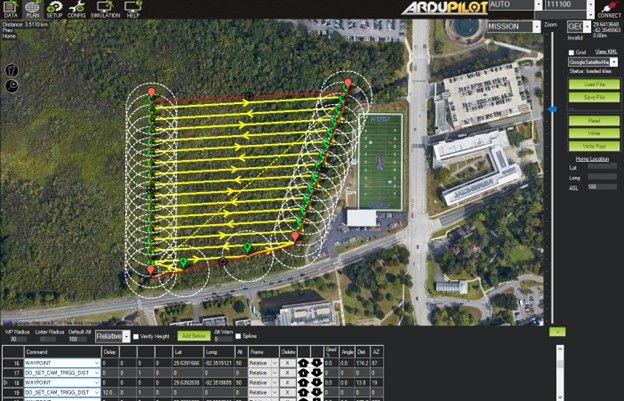
9. Once done, MP will ask for a home altitude, which is the altitude from which you will launch the drone. After all configurations are done, the result should appear similar to Figure 13.
Credit: J. Chintanadilok, UF Department of Computer Science and Engineering
10. In order to send the flight path to the drone, click on “Write” in the toolbar on the right side of the page. This will upload the flight plan to the UAS.
Auto grid has now been set up. When the drone is launched in the general area, it will now fly to the position of the second waypoint and begin capturing images. When the grid is complete, it will fly back to the launch location.
“Arming” the UAS and Starting a Mission
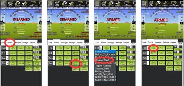
“Arming” the drone initializes the drone to the state where the motors can spin when the throttle is applied. Each drone manufacturer has a unique method to arm and disarm the drone using a radio transmitter; refer to the user manual for the proper procedure. Mission Planner allows an alternate process to arm and disarm the drone using only the field laptop (Figure 14).
On the Data page, locate and click on the “Actions” tab on the navigation bar below the HUD on the left side of the page (see Figure 14). Clicking on the Arm/Disarm button changes the HUD notification from “DISARMED” to “ARMED” after a few seconds.
Credit: J. Chintanadilok, UF Department of Computer Science and Engineering
In order to start flying the flight path created earlier, you must ensure that the drone is armed, and that the HUD reports no errors. If there are any unfamiliar errors, refer to Mission Planner forums (ArduPilot n.d.) or the knowledge base (ArduPilot Dev Team 2021a). In order to start the mission, locate the dropdown menu next to the “Do Action” button and select the “Mission_Start” option. Click on the “Do Action” button and then confirm the operation on the pop-up menu to begin the mission. If any abnormalities occur with the flight hardware or the mission, you can safely return the drone to the launch point by finding and selecting the “Return_To_Launch” option from the dropdown menu next to the “Do Action” button, and then clicking the “Do Action” button. After the flight concludes or terminates, make sure to disarm the drone to avoid potential accidents and to ensure the safety of all users and observers.
Additional ResourcesThe Mission Planner knowledge base (https://ardupilot.org/planner/index.html) is an excellent resource if you encounter any errors. YouTube videos by Linn Aerospace that illustrate a step-by-step process are linked here https://www.youtube.com/watch?v=rui2Trps2yc&ab_channel=LinnAerospace.
References
ArduPilot. n.d. https://discuss.ardupilot.org/
ArduPilot Dev Team. 2021a. “ArduPilot.” https://ardupilot.org/copter/index.html
ArduPilot Dev Team. 2021b. “Mission Planner Overview.” https://ardupilot.org/planner/docs/mission-planner-overview.html
ArduPilot Dev Team. 2021c. “What is a multicopter and how does it work?” https://ardupilot.org/copter/docs/what-is-a-multicopter-and-how-does-it-work.html
Liang, O. 2020. “FPV Drone Flight Controller Explained.” https://oscarliang.com/flight-controller-explained/
Linn Aerospace. 2015. “Mission Planner Part 1 – Introduction.” https://www.youtube.com/watch?v=rui2Trps2yc&ab_channel=LinnAerospace