Leaf wetness sensors are used to monitor the duration of leaf wetness events. Leaf wetness duration is an essential input in disease prediction models and decision support systems in Florida and elsewhere. Incorrect installation or lack of regular maintenance of these sensors may lead to errors in plant disease risk monitoring and negative impacts on yield. This publication provides detailed guidelines for the proper installation and maintenance of leaf wetness sensors and describes the most common problems found in field installations as well as potential solutions. A quick maintenance checklist and a summary table are provided to facilitate sensor installation and maintenance activities.
Introduction
Plant diseases reduce crop yield, crop quality, and growers' income while increasing production costs. There are ways of predicting the risk of fungal and bacterial disease occurrence by monitoring environmental conditions that affect the favorability for their occurrence, such as air temperature and leaf wetness duration (Gleason et al. 2008; Huber and Gillespie 1992; Wilson et al. 1990). In the last decade, improvements in both sensor technology and information and communications technology (ICT) have enabled better monitoring and disease risk prediction. However, data from sensors in general and leaf wetness sensors, in particular, have often been of questionable quality due to improper installation and maintenance (Sentelhas et al. 2007). This publication describes the proper installation procedure and use of common leaf wetness sensors, as well as common problems and solutions.
Leaf wetness is defined as the "presence of free water on the surface of the canopy," and it can be caused mainly by rainfall, dew, and overhead irrigation (Rowlandson et al. 2015). Leaf wetness duration (LWD) is the common measurement of how long plants remain wet during and after an event such as rainfall, irrigation, or morning dew. Favorable environmental conditions for disease development are specific to each host-pathogen interaction and are commonly inferred by the combination of temperature and LWD. Generally, the more favorable the environment temperature is to the optimal pathogen development, the shorter the necessary wetness duration, and vice versa (Huber and Gillespie 1992). Accurately measuring LWD poses a significant challenge to correctly estimating the risk of fungal disease infections. Leaf wetness duration may vary significantly from place to place, and it may be different even within the same plant (Gleason et al. 2008).
EDIS document AE502, Your Farm Weather Station: Installation and Maintenance Guidelines (https://edis.ifas.ufl.edu/ae502), provides basic guidelines for installing and maintaining a farm weather station. This publication provides more detailed information about the installation and maintenance of leaf wetness sensors (LWS), given the importance of LWD for disease risk monitoring in Florida and elsewhere.
Types of Sensors
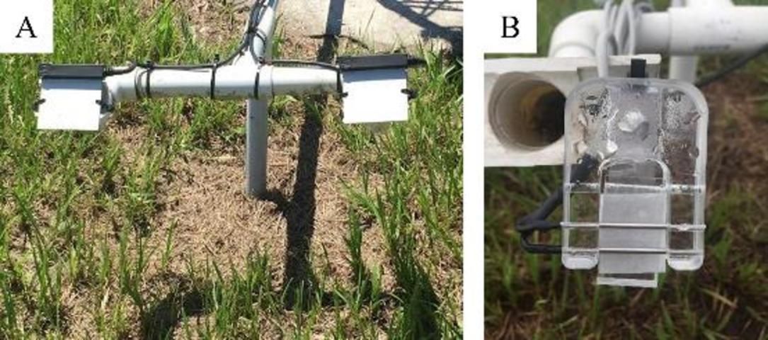
The most common electronic sensors used for leaf wetness detection are based on monitoring changes in the sensor's resistance or dielectric principle (Figure 1). Figure 1A shows a pair of flat-plate resistance sensors (Campbell 237L, Logan, UT), and Figure 1B shows a paper-based resistance sensor (Model IM521CD, Pessl Instruments, Austria). Both types of sensors are commonly used for leaf wetness duration monitoring. Davis and Hughes (1970) determined that unpainted flat-plate resistance sensors may not be able to detect small droplets of water (especially at the onset of dew development), which may form between the interlaced fingers of a sensor but do not bridge the wires. Painting allows these droplets to be absorbed by the paint and spread out for detection (Rowlandson 2011). The flat-plate sensors in Figure 1A were painted with two coats of white latex paint and heat-treated according to the recommendations by Sentelhas et al. (2004b).
Credit: T. B. Onofre, UF/IFAS
A resistive leaf wetness sensor measures the resistance or impedance between wires or electrodes, and a dielectric leaf wetness sensor measures the dielectric constant of the sensor's upper surface. Both sensors are based on the principle that wetness on the sensor changes the resistance or the dielectric constant (depending on the sensor type), which is measured by a datalogger (Gillespie and Kidd 1978; Getz 1991; Sentelhas et al. 2004; Sentelhas et al. 2007).
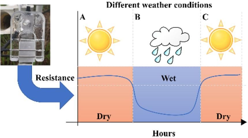
The illustration in Figure 2 shows the output of a resistive sensor for different weather conditions. The paper-based sensor measures the electrical resistance of a paper between two metal electrodes. In sunny conditions (Figure 2A), the paper is dry, and the resistance is high. During a wetness event (Figure 2B), the resistance drops, and the datalogger registers the amount of time the sensor is wet (leaf wetness duration). Once the sensor dries off, the datalogger stops the measurement of leaf wetness duration (Figure 2C).
Credit: T. B. Onofre, UF/IFAS
Proper Installation of Leaf Wetness Sensors (LWS)
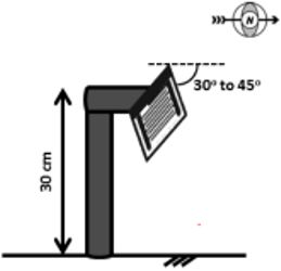
A leaf wetness sensor should be installed at a height of 30 cm, at a 30–45° angle to the ground facing north, if the installation site is in the Northern Hemisphere. The orientation angle (north for locations in the Northern Hemisphere) of the sensor is important; plants receive less sunlight on the northern side, causing the sensor to stay wet for more extended periods. The sensor should be placed in a location that is not affected by irrigation sprinklers (outside of the sprinklers' wet area) and in an area covered with turfgrass. The cables from the sensor to the datalogger should be buried or protected to avoid damage from animals and/or mowing (Sentelhas et al. 2007; Gleason et al. 2008; Rowlandson et al. 2015).
Proper Installation Summary (Figure 3):
- The LWS should be installed at a height of 30 cm (1 ft).
- It should face north if installed anywhere in the United States or in the Northern Hemisphere.
- It should be installed at a 30–45° angle to the ground.
- The ground surface should be covered with turfgrass.
- The sensor should be placed in a location that is not affected by irrigation sprinklers or other sources of moisture.
- The cables from the sensor to the datalogger should be buried to avoid damage from animals and/or mowing.
Credit: Adapted from Fraisse et al. (2017)—AgroClimate Workbook
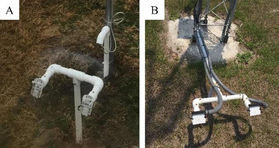
Below are two examples of what a proper installation looks like in the field (Figure 4). Figure 4A shows a pair of paper-based leaf wetness sensors (Pessl Instruments Leaf Wetness Sensor) with the cables buried and protected by a PVC tube. Figure 4B shows a pair of flat-plate sensors (Campbell 237L) installed at a FAWN (Florida Automated Weather Network) station. Researchers often use leaf wetness sensors in pairs to improve monitoring accuracy.
Credit: T. B. Onofre, UF/IFAS
Common Problems with LWS Installation and Maintenance
The most common problems with leaf wetness sensors (LWS) are:
- Improper installation:
- Problems with height, orientation, and angle of installation.
- Improper maintenance:
- Missing or damaged paper (in paper-based sensors);
- Herbicide application removing the grass surface;
- Dirty sensor;
- Sensor with cut wires; and
- Degraded sensor coating.
The sections below briefly describe, illustrate, and propose solutions for the problems listed above.
- Improper LWS Installation
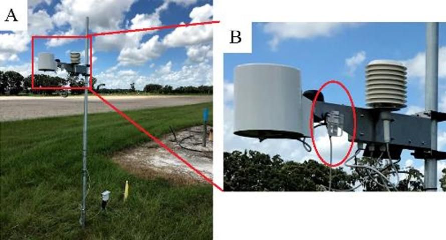
Improper installation is a common problem found with sensors installed in growers' farms. The most common issues we have found in the field are related to installation height and orientation. Improper installation of a paper-based leaf wetness sensor is shown in Figure 5. Figure 5A shows a weather station with a leaf wetness sensor installed at 6 ft (2 m), and Figure 5B shows more details of the leaf wetness sensor (inside of the red circle). This sensor installation may not represent leaf wetness conditions at the plants' height, potentially compromising disease risk prediction.
Credit: T. B. Onofre, UF/IFAS
Solution
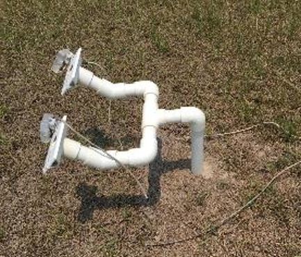
An inexpensive way to ensure proper installation is to build a PVC pipe mounting using ¾-inch tubes and curves, as shown in Figure 6. This PVC mounting was built using a total of 3 ft (91 cm) of ¾-inch tubes, three right-angle elbows, three T connectors, and two 45° elbows.
Credit: T. B. Onofre, UF/IFAS
2. Improper Maintenance
A) Missing or Damaged Paper
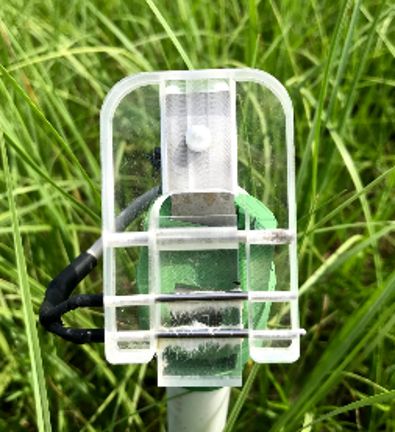
This is a common problem when using a paper-based leaf wetness sensor. The paper degrades over time, causing the sensor not to work correctly, as shown in Figure 7.
Credit: T. B. Onofre, UF/IFAS
Solution
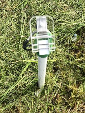
Replace the paper and set an alarm and notification in your calendar to check and replace the paper every month during the rainy season. Growers must pay special attention during the cropping season if they own a weather station with a paper-based LWS. Commercial strawberry growers in Florida need sensors to operate properly during fall and winter (October to March).
Credit: T. B. Onofre, UF/IFAS
B) Herbicide Application under the LWS
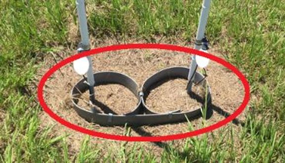
Growers use herbicides as part of lawn maintenance, but herbicide should not be applied under the sensor. Figure 9 shows an example of improperly applied herbicides that will affect LWD data for this site. Although the sensor site is clean, this may change the readings because the LWS is supposed to be installed over turfgrass.
Credit: T. B. Onofre, UF/IFAS
Solution
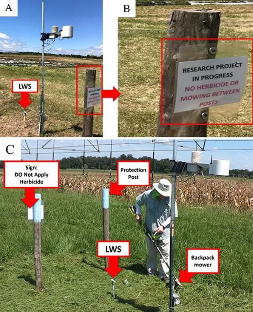
Install a "Do not apply herbicide" sign near the sensor and regularly mow the grass around sensors, as shown in Figure 10. The sign in Figure 10B was made for research purposes. Farmers should modify the sign according to their needs. By "no mowing" (Figure 10B), we mean do not mow with a tractor or heavy machinery. Instead, use a backpack mower with necessary personal protective equipment (PPE) (Figure 10C). As an additional protective measure, we installed posts near the weather station and sensors to prevent accidental damage from machinery in the field.
Credit: T. B. Onofre, UF/IFAS
C) Dirty Sensor
Leaf wetness sensors must be kept free from dirt, dust, debris, and bird droppings. During periods of pollination, a layer of pollen can develop on a sensor surface, and it will require frequent cleaning (Rowlandson et al. 2015). During the planting season, a weekly examination of the sensor is necessary. Otherwise, a monthly or biweekly inspection should be adequate for most locations.
Solution
Use water and a soft cloth to clean the surface of dirty sensors.
D) Sensor with Cut Wires
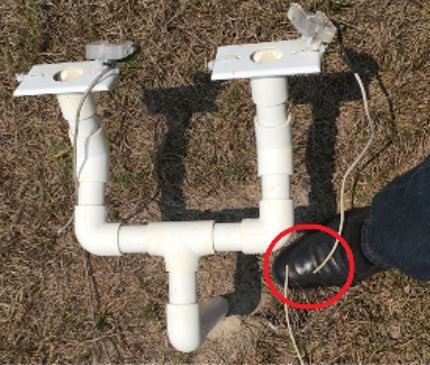
Exposed wires are susceptible to mowing machines (edge cutters, backpack, etc.), rodents, ants, and UV radiation. In Figure 11, both sensors had their wires cut, leading to significant losses of data.
Credit: T. B. Onofre, UF/IFAS
Solution
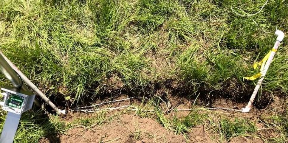
The best solution is to bury the LWS cables to protect them, as shown in Figure 12, where the cables were buried in a ditch of approximately 1ft (30 cm). In this scenario, a ½-inch PVC pipe with a length of approximately two feet and a right elbow were used in each side of the ditch to protect the sensor cable.
Credit: T. B. Onofre, UF/IFAS
E) Degraded Sensor Coating
In the past, we have observed the degradation of the surface in dielectric constant-based sensors (plate type of sensors, Figure 1B). The surface coating of dielectric constant-based sensors deteriorates due to weather conditions and exposure to UV radiation. The surface turns yellowish and becomes rougher, causing the sensor to underreport wetness time.
Solution
Replace the dielectric leaf wetness sensor every year or before the season if you notice the surface has changed from white to yellowish.
Conclusion
Leaf wetness sensors are essential for disease prediction and decision support systems. However, this type of sensor requires special attention and maintenance. An LWS must be installed and maintained according to a specific set of guidelines for optimal performance. Remember to install the LWS at 30 cm (1 ft), 30°–45° facing north (Northern Hemisphere), and bury the cables. Do not apply herbicides under your sensors. The sensors must be kept clean. If you have a paper-based sensor, you will need to replace the paper often. Setting reminders on your phone might help you maintain your sensor properly.
Appendix—Leaf Sensor Checklist
Proper Installation Checklist
- The LWS should be installed at the height of 30 cm (1 ft).
- It should face north if installed in Florida, anywhere else in the United States, or in the Northern Hemisphere.
- The LWS should be at a 30°–45° angle to the ground.
- The ground surface should be covered with turfgrass.
- The sensor should be placed in a location that is not affected by irrigation sprinklers or other sources of moisture.
- The cables from the sensor to the datalogger should be buried to avoid damage from animals and/or mowing.
Maintenance checklist:
Biweekly:
- Check for missing or damaged paper (Only for Pessl Instruments leaf wetness sensor).
- Use a backpack mower to carefully mow the grass underneath the sensor.
Monthly:
- Clean dirty sensors.
- Replace cut wires.
Yearly:
- Replace the dielectric leaf wetness sensor every year or if you notice the surface has changed from white to yellowish.
*CHECK THE SENSORS ANY TIME YOU NOTICE YOUR DATA ARE NOT COHERENT.
References
Davis, D. R., and J. E. Hughes. 1970. "A new approach to recording the wetting parameter by the use of electrical resistance sensors." Plant Dis. Rep. 54: 474–479.
Fraisse, C. W., G. W. Braun, W. R. Lusher, and L. R. Staudt. 2018. Your Farm Weather Station: Installation and Maintenance Guidelines. AE502. Gainesville: University of Florida Institute of Food and Agricultural Sciences. https://edis.ifas.ufl.edu/ae502
Gillespie, T. J., and G. E. Kidd. 1978. "Sensing duration of leaf moisture retention using electrical impedance grids." Can. J. Plant Sci. 58: 179–187. https://doi.org/10.4141/cjps78-027
Gleason, M. L., K. B. Duttweiler, J. C. Batzer, S. Elwynn Taylor, P. C. Sentelhas, J. E. B. A. Monteiro, and T. J. Gillespie. 2008. "Obtaining weather data for input to crop disease-warning systems: Leaf wetness duration as a case study." Scientia Agricola 65(SPE): 76–87. https://doi.org/10.1590/S0103-90162008000700013
Huber, L., and T. J. Gillespie. 1992. "Modeling leaf wetness in relation to plant disease epidemiology." Annual Review of Phytopathology 30(1): 553–577. https://doi.org/10.1146/annurev.py.30.090192.003005
Rowlandson, T. 2011. Leaf wetness: Implications for agriculture and remote sensing. Ph.D. dissertation. Ames: Iowa State University.
Rowlandson, T., M. Gleason, P. Sentelhas, T. Gillespie, C. Thomas, and B. Hornbuckle. 2015. "Reconsidering leaf wetness duration determination for plant disease management." Plant Disease 99(3): 310–319. https://doi.org/10.1094/PDIS-05-14-0529-FE
Sentelhas, P. C., T. J. Gillespie, M. L. Gleason, J. E. Monteiro, and S. T. Helland. 2004. "Operational exposure of leaf wetness sensors." Agric. For. Meteorol. 126: 59–72. https://doi.org/10.1016/j.agrformet.2004.05.009
Sentelhas, P. C., J. E. B. A. Monteiro, and T. J. Gillespie. 2004. "Electronic leaf wetness duration sensor: Why it should be painted." Int. J. Biomet. 48: 202–205. https://doi.org/10.1007/s00484-004-0200-z
Sentelhas, P. C., T. J. Gillespie, and E. A. Santos. 2007. "Leaf wetness duration measurement: Comparison of cylindrical and flat plate sensors under different field conditions." International Journal of Biometeorology 51(4): 265–273. https://doi.org/10.1007/s00484-006-0070-7
Wilson, L. L., L. V. Madden, and M. A. Ellis. 1990. "Influence of temperature and wetness duration on infection of immature and mature strawberry fruit by Colletotrichum acutatum." Phytopathology 80(1): 111–116. https://doi.org/10.1094/Phyto-80-111