Introduction
American black bears (Ursus americanus) are the most damaging vertebrate pest of honey bee (Apis mellifera L.) apiaries in North America (Lord and Ambrose 1981). Despite popular portrayals in cartoons and movies, bears seek out honey bee nests primarily to eat the protein-rich brood (larvae and pupae). The honey itself is a sweet treat (Sanford and Ellis 2009). While raiding hives, bears have the potential not only to decimate a honey bee colony's population, but also to damage the beekeeping equipment. Both of these result in economic losses for beekeepers.
Many top beekeeping and pollination states in the United States (Figure 1) fall within the range of the American black bear (Figure 2) (Clark et al. 2005). This increases the likelihood of beekeepers and bears interacting. Once bears get a taste of bees and honey, they often return to a bee yard (apiary) multiple times (Hygnstrom and Craven 1996; Oliver 2014). Thus, prevention is key when working to mitigate damage caused by bears. Most beekeepers keep bears away from their hives by constructing temporary or permanent electric fences around the apiary. The basic steps for installing a bear fence are detailed below.
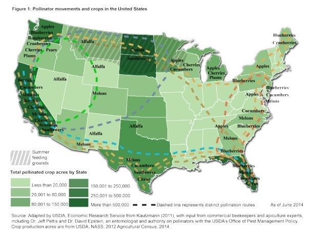
Credit: Bond, Plattner, and Hunt (2014).
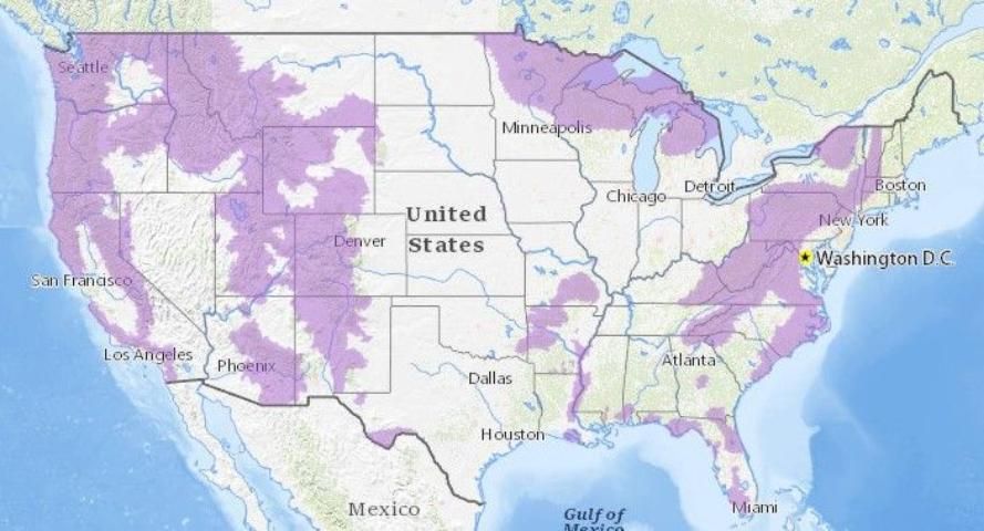
Credit: United States Geological Survey, https://www.usgs.gov/media/images/known-range-american-black-bear-ursus-americanus
Supplies and Tools
- Fence charger designed to power at least 5 miles (8 km) of fence line (solar used as example, but electric or battery-powered chargers are available)
- 5 feet (~1.5 meters) heavy-duty t-posts (avoid light-duty posts typically used for gardens)
- T-post insulators (2-inch/5-cm standoffs may be helpful around corners); you will need three insulators per t-post used
- High-tensile fence wire, 12- or 14-gauge (high-tensile wire is more resistant to elongation/sagging)
- Insulated fence handles with internal springs
- 6 feet (~1.8 meters) galvanized steel grounding rod and clamp
- Fence tester
- T-post driver
- Fencing pliers (for cutting and twisting wire)
- Sledge hammer
There are several variations of the materials suggested for constructing a bear fence. The majority of supplies are available at agriculture supply and home improvement stores nationwide.
Site Considerations
Beyond the normal factors taken into account when selecting a site for an apiary, a few things must be considered when constructing a bear fence. While it may seem convenient, it is not recommended to use trees as the posts for your bear fence. Bears are clever enough to climb the tree and drop down inside the electric fence, thus avoiding the fence entirely. Pay attention to the distance between the fence and the hives. At least three feet of space will keep hives out of range of bears reaching through the fence to knock them over. Ensure plentiful space between the fence and trees and anything else bears could use to climb over the fence. Eliminate brush and vegetation that may interfere with the function of the electric fence.
Steps of Fence Installation
Installing Posts and Wire
- With a t-post driver, install corner t-posts with the studded side of the posts facing outward, keeping in mind spacing between fence and hives and fence and exterior objects. All t-posts should be driven at least 1.5 feet (0.3 m) into the ground.
- Install t-posts between the corners as needed, approximately every 8 feet (2.4 m). If you will need to back a truck or trailer into the enclosure to unload bees, consider leaving one post out to allow such traffic.
- Install a t-post inside the enclosure in one corner (Figure 3). Space these two posts (the corner post and the one installed inside the fence) 1.5 feet (0.45 m) apart to allow sufficient distance for the jumper wire to connect the two.
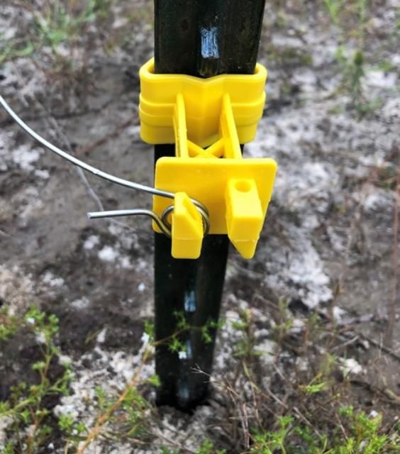
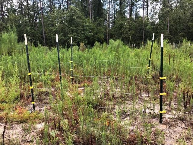
- Attach three insulators to each perimeter t-post at approximately 8 inches (0.2 m), 20 inches (0.51 m), and 32 inches (0.81 m) from the ground. This arrangement places a bottom wire close enough to the ground to dissuade bears from crawling under the fence but also high enough with the middle and top wires so the bear cannot crawl through or over the wires (Figure 4).
- Starting at the corner with the interior t-post, wrap the wire around the bottom insulator to hold the end of the wire in place (Figure 5).
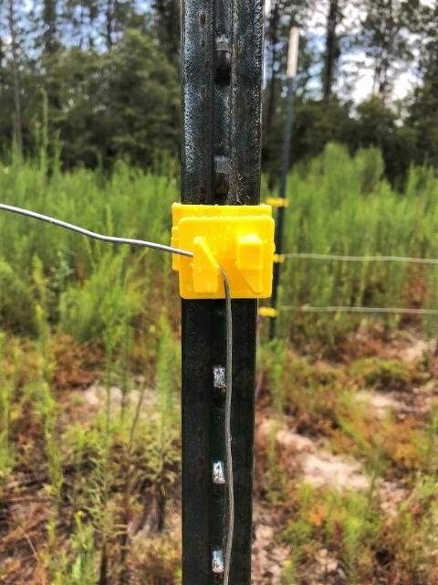
- Run the wire through the bottommost insulator on each t-post around the perimeter. You may choose to unroll the wire as you run it through the insulators, or you may prefer to first walk around the perimeter of the enclosure while unrolling wire and then go back and run the wire through each insulator. If working alone, it may be faster to unroll the wire first, then run through each insulator. When working with a partner, your partner can feed out wire as you run through insulators. Be sure to tighten or put tension on the wire as you round each corner.
- When you return to the insulator where you started, simply run the wire through the insulator a second time, then straight up to the middle level of insulators (Figure 6). Do NOT cut the wire between levels.
- Repeat Step 6 for the middle and top levels. When you reach the final insulator on the top level, leave a 2-foot (0.6 m) tail beyond the insulator and cut the wire (Figure 7). This will serve as your jumper wire to the fence charger.
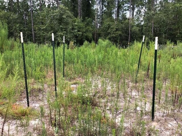
Credit: K. Post, UF/IFAS
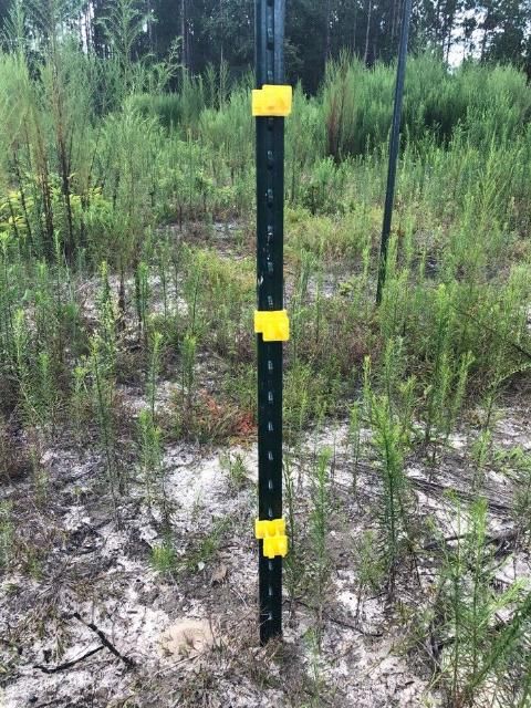
Credit: K. Post, UF/IFAS
Credit: K. Post, UF/IFAS
Credit: K. Post, UF/IFAS
Credit: K. Post, UF/IFAS
Creating a Gate
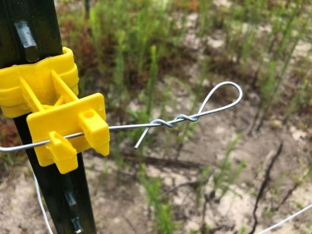
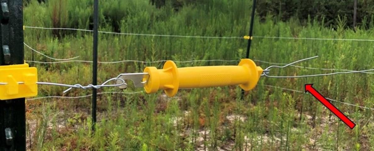
9. At this point, you can add a gate for easy entry into the bee yard. Cut one level of the wire approximately 6 inches (0.15 m) from one of the corners (preferably not the corner where you created the jumper wire). Twist this 6 inches (0.15 m) of wire into a loop (Figure 8). Hang the fence handle by its hook end on this short loop.
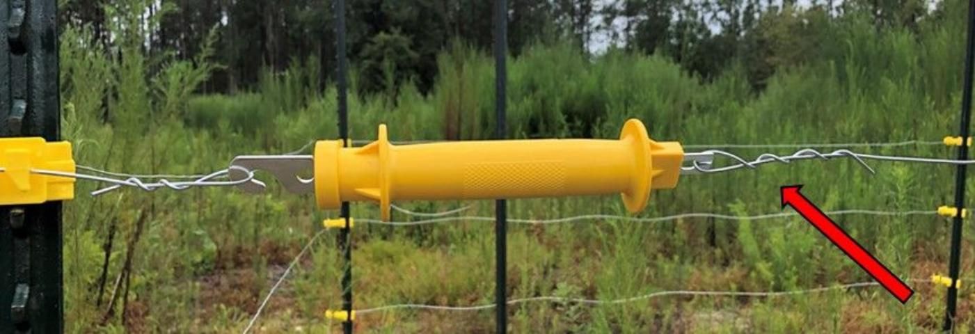
10. Holding the fence handle horizontally while hooked in the short loop, take the long loose end of wire from that level and run it through the spring end of the handle (Figure 9). Pull it back onto itself to create enough tension to engage the spring of the handle, then twist the wire around itself (Figure 10).
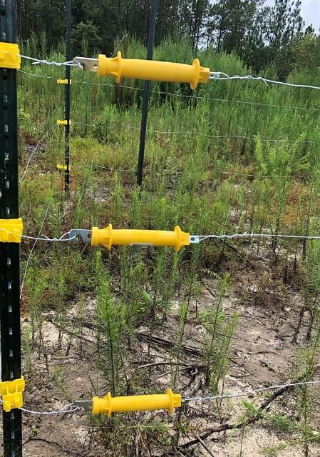
11. Repeat Step 9 and Step 10 for the remaining two levels of fence wire. You should now have a three-strand gate at one corner of the enclosure (Figure 11).
Credit: K. Post, UF/IFAS
Credit: K. Post, UF/IFAS
Credit: K. Post, UF/IFAS
Credit: K. Post, UF/IFAS
Adding Charge and Ground
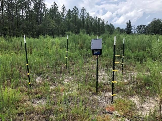
12. Attach the fence charger to the interior t-post. If using a solar charger, face the solar panel south to catch the most sun in the Northern Hemisphere or face it to the north in the Southern Hemisphere. Most solar fence chargers have a slot on the back of the charger designed to slide over the top of a fence post. Other models may require a mounting adapter or modified attachment methods. Mounting the fence charger inside the electric fence will help protect the charger from damage or removal by bears.
13. Make sure the charger is switched off before continuing! Attach the jumper wire to the positive terminal on the fence charger. On most fence chargers, the positive terminal will be red, indicated by a plus sign (+), or indicated by a lightning bolt symbol (?) (Figure 12).
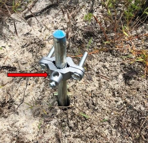
14. Using the sledge hammer, drive the grounding rod into the ground near the fence charger. About 6 inches (0.15 m) of grounding round should remain exposed (Figure 13).
15. Affix the grounding rod clamp to the grounding rod (Figure 13). Cut a section of wire that will reach from the fence charger to the clamp. Connect one end of the wire to the ground terminal on the charger and the other end of the wire through the grounding rod clamp.
Credit: K. Post, UF/IFAS
Testing the Fence
16. Making sure no part of your body is touching the fence wires, turn on the fence charger. Test the voltage using a fence tester (Figure 14). Depending on the fence charger, the tester should indicate 6000 to 8000 volts. If the reading is lower, there may be interference.
17. Listen to snaps or pops near the fence. This usually occurs in areas where vegetation is in contact with the fence wire or the fence is otherwise grounding out. Control vegetation within 2 to 3 feet (0.6 to 0.9 m) around the fence to prevent grounding the wires. Using a weed whacker or applying herbicides are most effective and portable for apiaries. Always turn the charger off before adjusting the fence or surrounding vegetation.
18. Once your fence is free of interference and functioning properly, it is ready to protect your hives from bears (Figure 15).
Credit: K. Post, UF/IFAS
Selected Resources
Bond, J., K. Plattner, and K. Hunt. 2014. "Fruit and Tree Nuts Outlook: Economic Insight." FTS-357SA, USDA Economic Research Service. https://bugwoodcloud.org/resource/files/6313.pdf
Clark, J. D., S. Dobey, D. V. Masters, B. K. Scheick, and M. R. Pelton. 2005. "American Black Bears and Bee Yard Depredation at Okefenokee Swamp, Georgia." Ursus 16 (2): 234–244.
Hygnstrom, S., and S. Craven. 1996. "Bear Damage and Abatement in Wisconsin." University of Wisconsin–Extension, R-10-96-2M-.75. Madison, Wisconsin, USA.
Lord, W. G., and J. T. Ambrose. 1981. "Bear Depredation of Beehives in the United States and Canada." American Bee Journal 121:811–815.
Oliver, R. 2014. "Electric Bear Fence for the Sierra Foothills." Scientific Beekeeping. http://scientificbeekeeping.com/scibeeimages/Bear-Fence-PDF-1.pdf
Sanford, M. T., and J. Ellis. 2009. Florida Bears and Beekeeping. ENY-105. Gainesville: University of Florida Institute of Food and Agricultural Sciences. https://edis.ifas.ufl.edu/aa133