The primary function of a pump is to transfer energy from a power source to a fluid, and as a result to create flow, lift, or greater pressure on the fluid. A pump can impart three types of hydraulic energy to a fluid: lift, pressure, and velocity. In irrigation and drainage systems, pumps are commonly used to lift water from a lower elevation to a higher elevation and/or add pressure to the water.
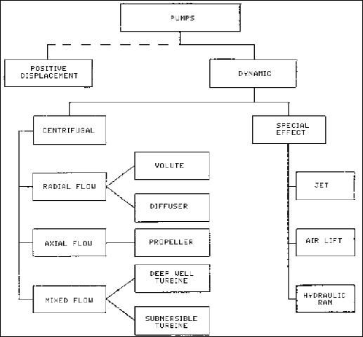
The classification of pumps used in this publication first defines the principle by which energy is added to the fluid, then identifies the means by which this principle is implemented, and finally, distinguishes among specific geometries commonly used. Under this system of classification, all pumps may be divided into two major categories: 1) dynamic pumps, where continuously added energy increases velocity of the fluid and later this velocity is changed to pressure, and 2) displacement pumps where periodically added energy directly increases pressure.
This publication will discuss only dynamic pumps which are commonly used for pumping water in agricultural applications such as irrigation and drainage. Displacement pumps have limited capacities and are not suitable for pumping large amounts of water required for irrigation or drainage. They are used mainly for chemical injection in agricultural irrigation systems. Displacement pumps are discussed in another publication.
Dynamic pumps described in this publication can be classified as one of several types of centrifugal pumps and a group of special effect pumps (Figure 1).
Centrifugal Pumps
In centrifugal pumps, energy is imparted to a fluid by centrifugal action often combined with propeller or lifting action. Centrifugal pumps can be classified by impeller shape and characteristics. Impellers are grouped according to the major direction of flow with respect to the axis of rotation. A continuous range in impeller types can be found. They vary from the radial-flow type (which develops head mainly by the action of centrifugal force), through mixed-flow types, to the axial flow type (which develops most of its head by the propelling or lifting action of the vanes).
With respect to type of impeller, all centrifugal pumps can be classified into the three following groups:
-
Radial-flow pumps
-
Axial-flow pumps
-
Mixed-flow pumps
In addition, a centrifugal pump can be classified in one of four major groups depending on its design and application (Figure 1):
-
Volute pumps
-
Diffuser pumps
-
Turbine pumps
-
Propeller pumps
Table 1 presents advantages and disadvantages of various centrifugal pumps. This comparison may be helpful in selecting a centrifugal pump for a particular application. (also see Table 3)
Further subclassification of centrifugal pumps distinguishes among the number of water inlets to the impeller. There are single suction impellers and double suction impellers.
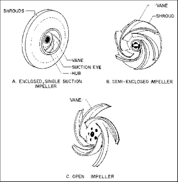
Finally, the mechanical construction of the impeller itself provides an additional classification (Figure 2). The impeller can be:
-
Enclosed with shrouds or side walls
-
Open with no shrouds
-
Semi-open or semi-closed.
Most irrigation pumps use enclosed or semi-enclosed impellers. Pumps with open impellers are usually used for pumping liquids with large particles and may be advantageous in drainage or when animal waste is applied through an irrigation system. Open impellers require frequent adjustments since the clearance between the impeller and the housing is critical.
Radial-Flow Pumps
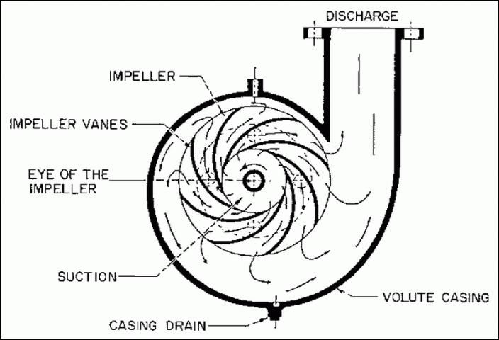
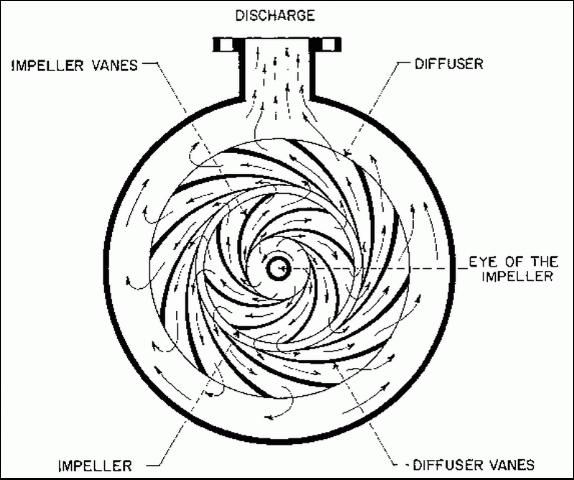
Basically, a centrifugal radial-flow pump has two main parts: 1) a rotating element (impeller and shaft) and 2) a stationary element (casing, stuffing box and bearings). Water enters the pump near the axis of the high-speed impeller, and by centrifugal force is thrown radially outward into the pump casing. The velocity head imparted to the fluid by the impeller is converted into pressure head by means of a volute (Figure 2) or by a set of stationary diffusion vanes (Figure 3) surrounding the impeller.
Volute Pumps
The centrifugal volute pump is the most common type of radial-flow centrifugal pump. It has an impeller housed in a progressively widening spiral casing as shown in Figure 2 . Water enters the eye of the impeller and is thrown radially outward. This type of pump does not have diffuser vanes to reduce the velocity of the water. Instead, velocity is reduced by the shape of the volute itself. This design creates an unequal pressure distribution along the volute which may result in a heavy thrust load on the impeller, creating deflection of the shaft, and increasing the probability of its failure.
Volute pumps can be single-suction or double-suction pumps. A single-suction pump impeller is exposed to a large axial hydraulic thrust resulting from the unbalanced hydraulic pressures on the impeller. In a double-suction pump, water is fed from both sides of the impeller, significantly improving its hydraulic balance. As a result, double-suction volute pumps can produce higher pressures than single-suction pumps.
Volute pumps are commercially available as single-stage (single impeller) or multistage (multiple impellers) pumps. The main reason for the multistage configuration is to increase the head produced by the pump. If a multistage pump has single suction impellers, the impellers are usually arranged with equal numbers discharging in opposite directions to counteract the hydraulic imbalance on each of the impellers.
Volute pumps are used where irrigation water is obtained from depths generally less than 20 ft. The exact value of possible lift is determined by the net positive suction head required by the pump and other factors as discussed later in this publication.
Diffuser Pumps
In a diffuser-type centrifugal pump, the impeller is surrounded by a ring of fixed diffuser vanes that provide enlarging passages in which the velocity of the water leaving the impeller is reduced, and as a result pressure is increased (Figure 4). The diffuser vanes provide a more controlled flow and allow a more efficient conversion of velocity into pressure than volute pumps. Shock losses are small since the change from velocity to pressure takes place gradually. Diffuser pumps, especially large ones, often have efficiencies over 90 percent. Diffuser pumps have the additional advantage of a balanced radial loading on the impeller, which reduces the chance of shaft failure due to fatigue.
Diffuser pumps are usually selected for high head applications (high pressure). As with volute pumps, diffuser pumps can be single or multistage depending on pressure requirements.
Axial-Flow Pumps
Axial-flow pumps, also called propeller pumps, produce flow by the lifting action of the propellers. Axial-flow pumps are designed for conditions where the capacity is relatively high and the head developed by the pump is low.
An axial pump does not produce high pressure or lift, but can have significant flow capacity if the pump is large enough. Most axial-flow pumps operate on installations where suction lift is not required. Generally, these pumps are mounted vertically or on an incline from vertical since it is necessary to submerge the impeller of an axial-flow pump. In some applications where high volumes of water are required and ample submergence above the pump is available, it is possible to mount an axial-flow pump in a horizontal position.
Mixed-FLow Pumps
Mixed-flow centrifugal pumps use both centrifugal force and some lifting action to move water. Water is discharged both radially and axially into a volute-type casing. The process is a combination of processes occurring in volute and axial-flow types of pumps. Mixed-flow impellers are often used in deep-well turbine and submersible turbine pumps.
Deep-Well Turbine Pumps
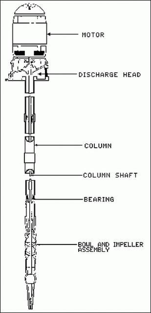
Under this category are grouped all types of pumps that are suspended by the discharge column within which the drive shaft is located (Figure 5). The name, deep-well turbine pump, is applied only to pumps operating on the centrifugal principle and having diffuser vanes within the bowl or case. They can be single-stage or multistaged for higher pressure applications. Pump bowls which contain impellers and diffusers are located below the water surface, and they should be submerged under pumping conditions. The drive shaft is located in the center of a discharge pipe and it can be either oil or water lubricated.
Submersible Turbine Pumps
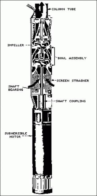
A submersible turbine pump is a turbine pump that is close-coupled to a submersible motor which is attached to the lower end of the pump (Figure 6). This eliminates the long shaft required for deep-well turbine pumps. Submersible pumps are primarily deep-well pumps; however, they are sometimes used under conditions where the depth of water changes significantly during the season and may drop below the level required for the centrifugal volute or diffuser pump.
Important Concepts for Centrifugal Pumps
Important concepts associated with the operation of centrifugal pumps include pump efficiency, net positive suction head, specific speed, affinity laws, cavitation, and priming. Good design, efficient operation, and proper maintenance require understanding of these concepts.
Pump Efficiency
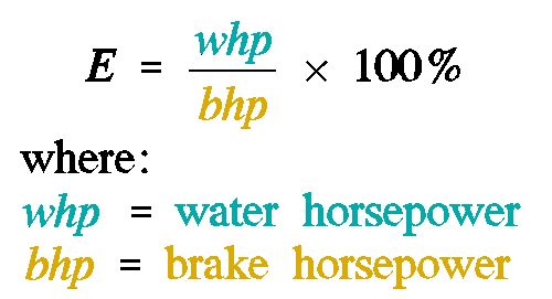
The efficiency of a pump is a measure of its hydraulic and mechanical performance. It is defined as the ratio of the useful power delivered by the pump (water horsepower) to the power supplied to the pump shaft (brake horsepower). The efficiency of the pump is expressed in percent and can be calculated using Equation 1: To calculate water horsepower the flow rate in gpm and the total dynamic head (TDH) in feet must be known. Water horsepower can be calculated using Equation 2: The efficiency of a pump is determined by actual test. All parameters required for the determination of water horsepower are recorded while brake horsepower is measured. Then, equations (1) and (2) are used to calculate the efficiency of the pump. The efficiency range to be expected varies with the pump size, type and design. However, it is normally between 65 and 80 percent. A pump should be selected for a given application so that it will operate close to its point of maximum efficiency.

Suction Lift
The absolute pressure on the water at the water source is the driving force for the water moving into the eye of the impeller. Theoretically, if a pump could create a perfect vacuum at the eye of the impeller, and if it were operating at sea level, the atmospheric pressure of approximately 14.5 psi would be the driving force pushing water into the eye of the impeller. This pressure could lift water a distance of 34 ft. (1 psi = 2.31 ft. of water). In practice, this lift is much smaller due to lack of perfect vacuum in the impeller and friction losses in the intake pipe. The practical value of maximum lift differs between pumps, but it is usually no greater than 20 ft. If the pump is submerged under water, static water pressure is an additional driving force pushing water into the eye of the impeller and it must be added to the atmospheric pressure. Each foot of water above the eye of the impeller will add 0.43 psi of pressure to the driving force.
Net Positive Suction Head
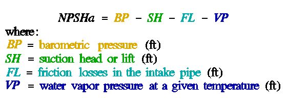
Net positive suction head available (NPSHa) is the absolute pressure of the water at the eye of the impeller. It is atmospheric pressure minus the sum of vapor pressure of the water, friction losses in the intake pipe, and suction head or lift. Since any variation of these four factors will change the NPSHa, NPSHa should be calculated using Equation 3: Suction head (SH) must be added instead of subtracted if the water source is located above the eye of the pump impeller (submerged pump). An accurate determination of NPSHa is critical for any centrifugal pump application.
The NPSHr (Net Positive Suction Head required) is a measure of the head necessary to transfer water into the impeller vanes efficiently and without cavitation (see the discussion of cavitation in a later section of this publication). The NPSHr required by a specific centrifugal pump depends on the pump design and flow rate. It is constant for a given head, flow, rotational speed and impeller diameter. However, it changes with wear and different liquids since it depends, respectively, on the impeller geometry and on the density and viscosity of the fluid. For a given pump NPSHr increases with increases in pump speed, flow rate, and water temperature.
The value of NPSHr is provided by the manufacturer for each specific pump model and it is normally shown as a separate curve on a set of pump characteristic curves. To avoid cavitation NPSHa must be always equal to or greater than NPSHr.
Specific Speed
Two pumps are geometrically similar when the ratios of corresponding dimensions in one pump are equal to the same ratios of the other pump. Specific speed is a constant for any geometrically similar pump. It is an index number correlating pump flow, head and speed at the optimum efficiency point which classifies pump impellers with respect to their geometric similarity. Specific speed is usually expressed as shown in Equation 4: It should be noted that for a double suction impeller the flow (Q) is taken as half of the total flow.
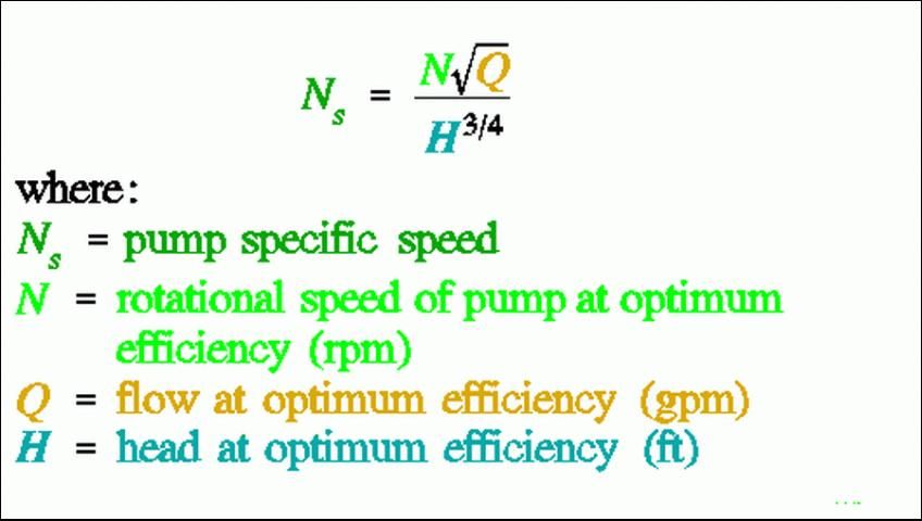
The specific speed is an index which is used when selecting impellers to meet different conditions of head, capacity, and speed. Knowing this index is very helpful in the determination of the maximum permissible suction lift, or minimum suction head, which is necessary to avoid cavitation under different capacities, heads and pump speeds. For a given head and capacity, suction lift is greater for a pump with lower specific speed.
The calculation of specific speed allows for determination of the pump type required for a given set of conditions to be determined. Usually high head impellers have low specific speeds and low head impellers have high specific speeds. (see Table 2)
There is often an advantage in using pumps with high specific speeds since, for a given set of conditions, their operating speed is higher, and the pump is therefore smaller and less expensive. However, there is also some trade-off since pumps operating at higher speeds will wear faster.
Affinity Laws
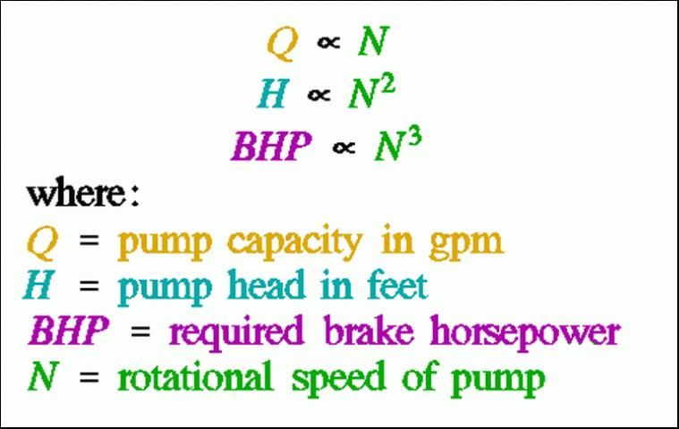
A set of formulas called affinity laws governs the performance of a given pump and the performance of geometrically similar pumps. Basically, affinity laws state that for a given pump, the capacity will vary directly with a change in speed, the head will vary as the square of speed, and the required horsepower will vary as the cube of speed or, mathematically, as shown in Equation 5: Assuming that impeller diameter is held constant, the mathematical relationships between these variables can be expressed as shown in Equation 6: Basically, the above relationships mean that an increase in pump speed will produce more water at a higher head but will require considerably more power to drive the pump. These calculated values are very close to actual test results, provided pump efficiency does not change significantly. However, when conditions are changed by speed adjustment, usually there is no appreciable change in efficiency within the range of normal pump operation speeds (6).
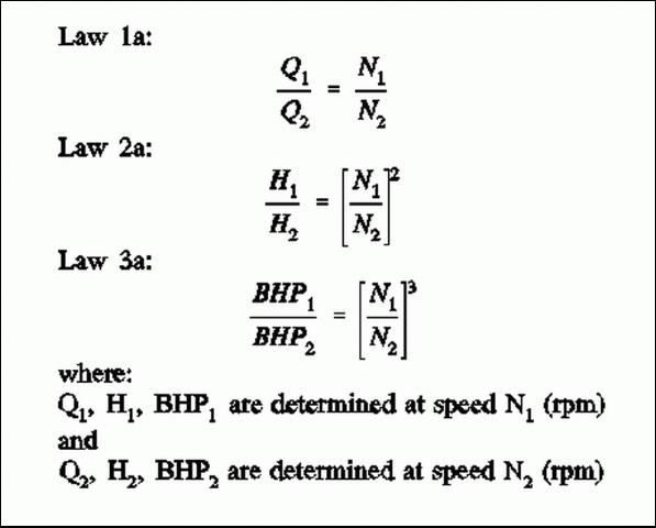
For increase in pump speed the NPSHr increases but it cannot be determined from the affinity laws. Also the laws do not say anything about how the efficiency of the pump will change with speed, but generally this is not a significant change. NPSHr and efficiency changes must be obtained from the pump manufacturer's data (pump characteristic curves).
The above equations assume that the diameter of the pump impeller is constant. In some cases the size of the impeller can be changed. Often a pump is very precisely matched to a specific application by trimming the impeller. It is not feasible to increase impeller diameter.
There is a second set of affinity laws (Equation 7), which describes the relationships between the same variables when the impeller size is changed under constant speed conditions. These laws relate the impact of impeller diameter changes to changes in pump performance. Since change of impeller diameter changes other design relationships in a pump, therefore, this second set of affinity laws does not yield the accurate results of the first three laws discussed above and must be applied with caution.
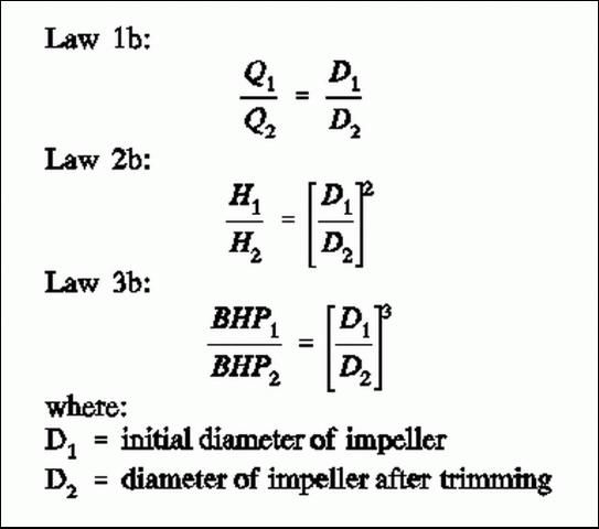
This second set of affinity laws strictly applies only to radial-flow pumps. They are only approximate for mixed-flow impellers. In addition, these equations only hold for small changes in impeller diameter. Calculations for a trim of more than 10 percent of the original diameter can be significantly in error.
Cavitation
Pump cavitation is defined as the formation of cavities on the back surface of an impeller and the resulting loss of contact between the impeller and the water being pumped (Walker, 1972). These cavities are zones of partial vacuum which fill with water vapor as the surrounding water boils due to the reduced pressure in the cavities. The cavities are displaced with the flowing water along the pump impeller surfaces toward the outer circumference of the impellers. As they move toward the circumference, the pressure in the surrounding water increases, and the cavities collapse against the impellers with considerable force. The force created by the collapse of the cavities often causes erosion and rapid wear of the pump impellers as well as a characteristic noise during pump operation.
The process of cavitation is caused by the reduction in pressure behind the impellers to the point that the water vaporizes (boils). Thus, it can be caused by any combination of factors which allow pressure to drop to that point, including inadequate submergence or excessive suction lift so that little pressure is available to move water into the pump, high impeller speeds which cause extremely low pressures to be generated behind the impellers, restricted pump intake lines which prevent water from moving readily into the pump, and high water temperatures which decrease the pressure at which water vaporizes.
Cavitation can occur in all types of pumps and it can create a serious problem. In some cases of mild cavitation, the only problem may be a slight drop in efficiency. On the other hand, severe cavitation may be quite destructive to the pump and result in pitting of impeller vanes. Since any pump can be made to cavitate, care should be taken in selecting the pump for a given system and planning its installation.
Pump manufacturers specify the Net Positive Suction Head required (NPSHr) for the operation of a pump without cavitation. Pump cavitation can be avoided by assuring that the net positive suction head available (NPSHa) is always greater than that required (NPSHr) by the pump.
Cavitation in Radial Flow and Mixed Flow Pumps
In radial-flow and mixed-flow types of centrifugal pump, when the water enters the eye of the impeller, an increase in velocity takes place. As a result of this velocity increase, water pressure is reduced as the water flows from the inlet of the pump to the entrance to the impeller vanes resulting in cavitation.
A concentrated transfer of energy during cavitation creates local forces capable of destroying metal surfaces. The more brittle the material which the impeller is constructed of, the greater the damage. In addition to causing severe mechanical damage, cavitation causes a loss of head, reduces pump efficiency, and results in noisy pump operation.
If cavitation is to be prevented, volute or diffuser pumps must be provided with water under absolute pressure which exceeds the NPSHr. The following conditions should be avoided in volute and diffuser pump installations:
-
Heads much lower than head at peak efficiency of pump.
-
Capacity much higher than capacity at peak efficiency of pump.
-
Suction lift higher or submergence head lower than recommended by manufacturer of the pump.
-
Water temperature higher than that for which the system was originally designed.
-
Speeds higher than manufacturer's recommendation.
Cavitation in Axial-Flow Pumps
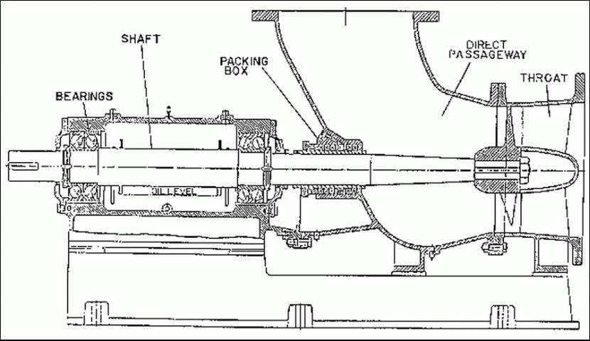
In axial-flow pumps cavitation cannot be explained in the same way as for radial-flow and mixed-flow pumps. The water enters an axial-flow pump in a large bell-mouth inlet and is guided to the smallest section, called the throat, immediately ahead of the propeller (Figure 7). The capacity at this point should be sufficient to fill the ports between the propeller blades. When the head is increased beyond a safe limit, the capacity is reduced to a quantity insufficient to fill up the space between the propeller vanes, creating cavities of almost a perfect vacuum. When these cavities collapse the water hits the propeller vane with a force sufficient to pit the surface of the vane. The first two cavitation prevention rules listed for volute and diffuser pump are different for an axial-flow pump. Avoid:
-
Heads much higher than head at peak efficiency of pump.
-
Capacity much lower than capacity at peak efficiency of pump.
The last three rules are the same for all centrifugal pumps.
Priming of Centrifugal Pumps
All centrifugal pumps must be primed by filling them with water before they can operate. The objective of priming is to remove a sufficient amount of air from the pump and suction line to permit atmospheric pressure and submergence pressure to cause water to flow into the pump when pressure at the eye of the impeller is reduced below atmospheric as the impeller rotates.
When axial-flow and mixed-flow pumps are mounted with the propellers submerged, there is normally no problem with repriming of these pumps because the submergence pressure causes water to refill the pumps as long as air can readily be displaced. On the other hand, radial-flow pumps are often located above the water source, and they can lose prime. Often, loss of prime occurs due to an air leak on the suction side of the pump. Volute or diffuser pumps may lose prime when water contains even small amounts of air or vapor. Prime will not be lost in a radial-flow pump if the water source is above the eye of the impeller and flow of water into the pump is unrestricted.
In some cases pumps are primed by manually displacing the air in them with water every time the pump is restarted. Often, by using a foot valve or a check valve at the entrance to the suction pipe, pumps can be kept full of water and primed when not operating. If prime is lost, the water must be replaced manually, or a vacuum pump can be used to remove air and draw water into the pump.
A self-priming pump is one that will clear its passages of air and resume delivery of liquid without outside attention. Centrifugal pumps are not truly self-priming. So called self-priming centrifugal pumps are provided with an air separator in the form of a large chamber or reservoir on the discharge side of the pump. This separator allows the air to escape from the pump discharge and entraps the residual liquid necessary during repriming. Automatic priming of a pump is achieved by the use of a recirculation chamber which recycles water through the impeller until the pump is primed, or by the use of a small positive displacement pump which supplies water to the impeller.
Special Effect Pumps
Jet Pumps
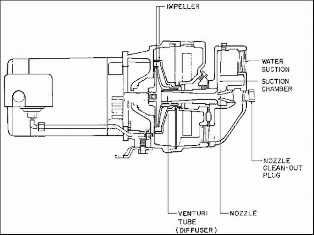
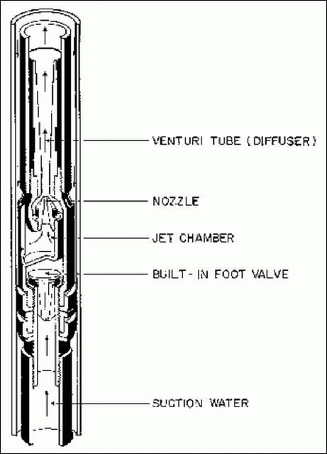
A jet pump is a combination of a volute centrifugal pump and a nozzle-venturi arrangement. The driving force lifting the water in this type of pump is provided by a high pressure nozzle which creates a low pressure region in a mixing chamber. This low pressure causes water to flow into the pump (Figure 8a and Figure 8b). A diffuser following the mixing chamber slows down the water and converts velocity head into pressure head. The jet nozzle is installed in the pipe conveying the water. For a shallow well the nozzle is frequently located outside the well next to the centrifugal pump (Figure 8a). However, for a deep well, the nozzle can be placed inside the well in the intake line (Figure 8b). This location increases the jet pump lift capability considerably beyond that which is practical for the volute centrifugal pump. The role of the centrifugal pump in a jet pump is to produce the flow to the nozzle and maintain the combined flow through the intake pipe beyond this point.
Jet pumps are self-priming, have no moving parts and do not require lubrication. Their efficiency is typically low (on average about 40%) and they provide low flows at high pressure. Because of this characteristic, they are not suitable for large scale irrigation. However, they are frequently used for home water supplies and irrigation of lawns and gardens.
Air-Lift Pumps
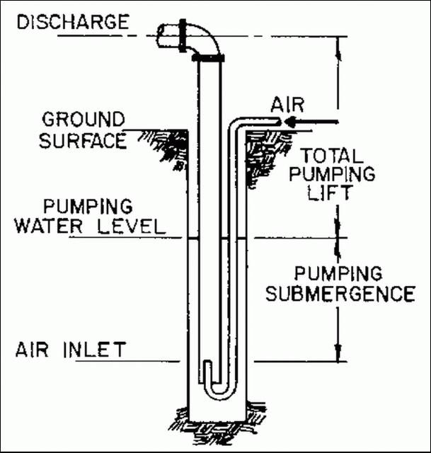
Air-lift pumps operate on the principle that a mixture of air and water will rise in a pipe surrounded by water. An air-lift pump basically consists of a vertical pipe partially submerged in water and an air supply tube allowing compressed air to be fed into the pipe at a considerable distance below the static water surface. The mixture of water and air is lighter than the water outside the pipe and it rises in the pipe (Figure 9). The head which can be produced depends on the depth of submergence of the air tube.
Air-lift pumps are relatively inefficient. Typical efficiencies range between 30 and 50 percent. Generally, air-lift pumping is most efficient when the static water level is high, the casing diameter is relatively small, and the well depth is not excessive in relation to the pressure capability of the compressor.
The volume of air needed to lift the water depends on the total pumping lift, the submergence, the length of air line, and the casing length and diameter. A useful rule of thumb for determining the proper compressor capacity for air-lift pumping is to provide about 3/4 cfm (cubic feet per minute) of air for each 1 gpm of water at the anticipated pumping rate.
Air-lift pumps have some advantages over the other pumps discussed above. They do not have any moving parts, can be used in a corrosive environment, and are easy to use in irregularly shaped wells where other deep well pumps cannot fit. Air-lift pumps are not available from suppliers, but they are very simple to build. The main disadvantages of air-lift pumps are their low efficiencies and requirement of a very large submergence as compared to other pumps.
Hydraulic Ram Pumps
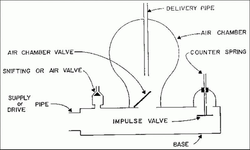
A hydraulic ram pump is a motorless low flow rate pump. It uses the energy of flowing water to operate (Figure 10). It is suitable for use where a large flow rate is not required. The flow rate of typical commercially available units is limited to approximately 14 gallons per minute or 20,000 gallons per day. The head produced by the pump depends on quantity and velocity of water flow at the pumping source. Water can be lifted up to 400 feet depending upon the quantity and velocity of water flow in the delivery pipe. Hydraulic ram pumps can be used for domestic water supply or livestock watering. Usually, their flow rates are too small to consider them for other applications, such as irrigation. For more information on operation and selection of hydraulic ram pumps see Agricultural Engineering Fact Sheet AE-19.
References
Driscoll, F.G. 1986. Groundwater and Wells. Johnson Division, St. Paul, MN.
Harrison, D.S. 1980. Hydraulic Ram Pumps. AE-19. Gainesville: University of Florida Institute of Food and Agricultural Sciences.
Holland, F.A. and F.S. Chapman. 1966. Pumping of Liquids. Reinhold Publishing Corporation, New York.
Hydraulic Handbook. 1979. Colt Industries, Fairbanks Morse Pump Division, 3601 Fairbanks Avenue, Kansas City, KS 66110.
Jensen, M.E. 1980. Design and Operation of Farm Irrigation Systems. American Society of Agricultural Engineers, St. Joseph, MI 49085.
Karassik, I.J., W.C. Krutzsch, W.H. Fraser and J.P. Messina. 1976. Pump Handbook. McGraw-Hill Book Company, New York.
Peerless Pump Technical Data. 1987. A Sterling Company, PO Box 7026, Indianapolis, IN 46206.
Walker, R. 1975. Pump Selection - A Consulting Engineer's Manual. Ann Arbor Science Publishers Inc. P.O. Box 1425, Ann Arbor, MI.