Methods of Chemical Injections
Chemical application through irrigation systems is called chemigation. Chemigation is typical for fertilizer application (fertigation) through irrigation systems. The primary reason for chemigation is economics, as a chemical application via irrigation is often less expensive than other methods. Another advantage is the ability to apply chemicals only when needed and in required amounts. This "prescription" application both follows plant needs much closer than traditional methods and minimizes the possibility of environmental pollution. Through chemigation, the chemical application is only in specified amounts, and thus, large quantities are not subject to leaching losses if heavy rainfalls follow applications. Additional advantages of chemigation include less operator hazard and possibly reduced amounts of chemicals (Ebrahimian, 2014).
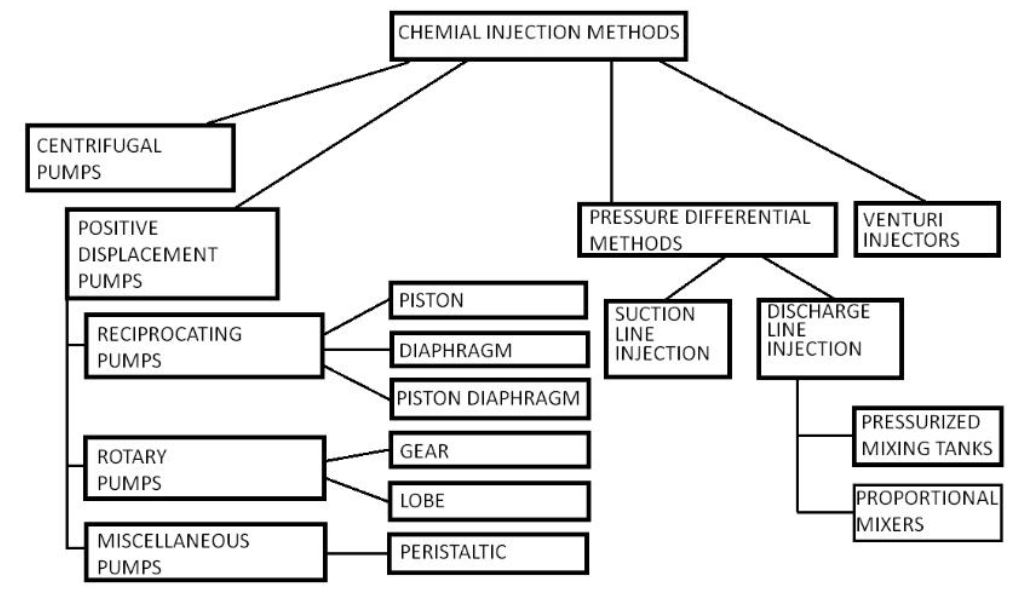
There are several methods of chemical injection into an irrigation system (Figure 1). These methods have four major groups: centrifugal pumps, positive displacement pumps, pressure differential methods, and methods based on the venturi principle (Kowalski, 2001). Specific methods further subdivide these four groups (Figure 1). In addition, some injectors use a combination of these methods. This publication will discuss each group of chemical injectors, their applications, and their advantages and disadvantages (Table 1).
Credit: undefined
Centrifugal Pumps
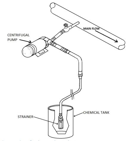
Small radial flow centrifugal pumps (booster pumps) can inject chemicals into irrigation systems. A detailed description of the principle of operation of a centrifugal pump is in UF/IFAS Extension Circular 832 (Haman, 1989). Fluid enters the centrifugal pump near the axis of the high-speed impeller and, by centrifugal force, is thrown radially outward into the pump casing. The velocity head imparted to the fluid by the impeller is converted into a pressure head using the volute or by a set of stationary diffusion vanes surrounding the impeller (Figure 2) (Karassik, 2012).
Credit: undefined
For a centrifugal pump to operate as an injector, it is necessary that the pressure produced by the pump be higher than the pressure in the irrigation line. However, the flow rate of the chemical from the pump depends on the pressure in the irrigation line. The higher the pressure in the irrigation lines, the smaller the flow rate from the injection pump. Because of that, centrifugal pumps require calibration while operating. This pump is not recommended for use when injecting toxic chemicals where the injection rate requires precise control (Purcell, 1997).
Positive Displacement Pumps
The injection of chemicals into a pressurized irrigation system frequently uses positive displacement pumps. Positive displacement pumps are either reciprocating, rotary, or miscellaneous (Figure 1), depending on the mechanism used to transfer energy to the fluid. Reciprocating pumps include piston, diaphragm, and combination piston/diaphragm pumps -- all commonly used for chemical injection into irrigation systems. This publication does not discuss rotary and miscellaneous pumps, which are typically not for chemical injections. Gear and lobe rotary pumps are occasional exceptions. Also, peristaltic pumps are only when low injection rates are required. Therefore, this publication briefly discusses gear, lobe, and peristaltic pumps. An interested reader may refer to the IFAS Extension Circular 826 (Haman, 1989) for a detailed description, typical applications, and discussion of the advantages and disadvantages of the various positive displacement pumps used in agriculture.
A positive displacement pump moves a constant volume of fluid from the intake to the discharge side of a pump. Theoretically, the volume displaced by the pump should be independent of the pressure encountered at the discharge point. However, this is not necessarily true for all pumps classified as positive displacement pumps. As in a mechanically driven diaphragm pump, if the internal parts of the pump can deform due to the increased pressure, the pump displacement volume will change, and the injection rate will not be constant. Furthermore, excessive pressure at the discharge may also result in some backflow through the clearances of the pump parts, for example, between the gears and the gear pump housing. Piston, fluid-filled diaphragm, and piston/diaphragm pumps come closest to being ideal positive displacement pumps and provide a constant flow rate independent of the discharge pressure. However, even with these pumps, excessive discharge pressures should be avoided (for example, due to a closed valve in a discharge line) because excessively high pressures may result in pump or line damage (Stewart, 2019).
Reciprocating Pumps
Reciprocating pumps are pumps in which a piston or a diaphragm displaces a given amount of chemical with each stroke. The change in the internal volume of the pump creates high pressure, which forces chemicals into the discharge pipe. These pumps are classified as piston pumps, diaphragm pumps, or a combination of piston and diaphragm.
In most diaphragm, piston, and diaphragm/piston combination pumps rotary motion of a drive wheel is transformed into reciprocating motion of a cylinder or a diaphragm.
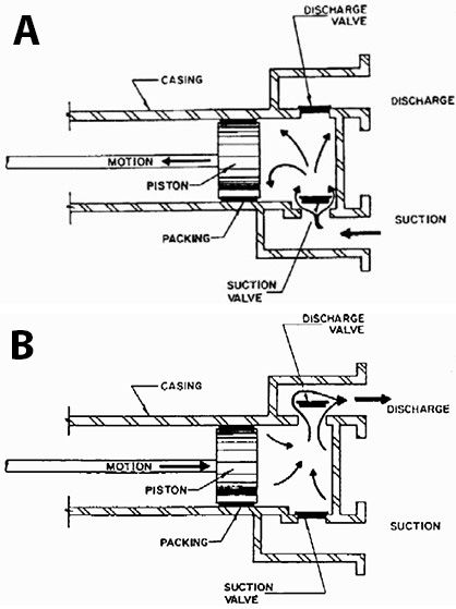
The operation of a piston pump is similar to the cylinder of an automobile engine. On an intake stroke (Figure 3a), the chemical enters the cylinder through the suction check valve. On a compression stroke (Figure 3b), the chemical is forced into the discharge line through the discharge check valve (Botermans, 2013).
Credit: undefined
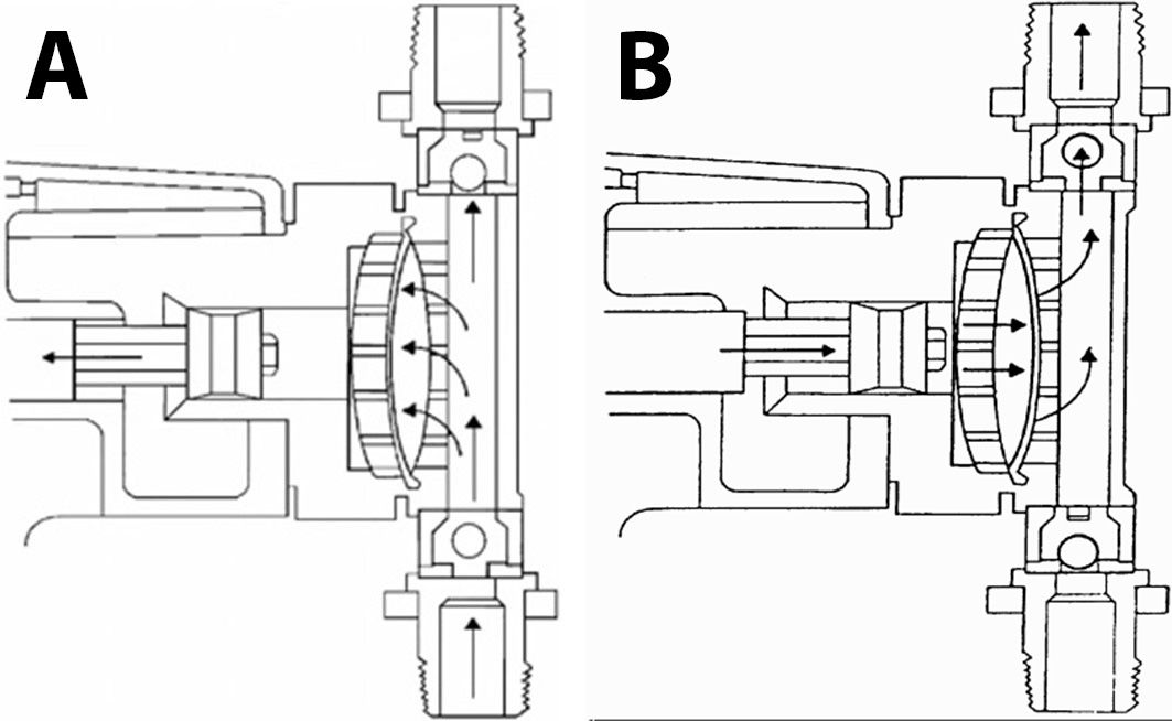
Diaphragm pump operation is similar to that of a piston pump. The pulsating motion is transmitted to the diaphragm through a fluid or a mechanical drive and then through the diaphragm to the chemical being injected (Figure 4a and Figure 4b).
Credit: undefined
Combination pumps usually contain a piston that forces oil or other fluid against a diaphragm, displacing the concentrated chemical. The advantage of these pumps is that they combine the high precision of a piston pump with the resistance to chemicals characteristic of diaphragm pumps.
Reciprocating pumps are often electrically driven. The chemical injection rate from an electrically driven pump is approximately constant regardless of the water flow rate. Thus, the injection rate must be adjusted between zones if the flow rate is not constant to all zones (Bloch, 1997).
To assure constant concentration of the chemical in the irrigation line, an electrically driven injector can be equipped with a water flow sensor to detect changes in flow rate and automatically adjust the speed of the injector or injection time. The other possibility is to measure the conductivity of the irrigation water (if injecting fertilizers) and use this information for automatic adjustment. Different chemicals require recalibration of sensors measuring conductivity.
A water motor drives some piston and diaphragm pumps. As water flows through the injector, it causes a cam to turn and push a piston back and forth. In a diaphragm pump, the piston or cam motion transmits to the diaphragm. Consequently, since the revolution of the cam depends on the flow rate of water in the irrigation system, oscillation of the piston and diaphragm also varies with the water flow rate. In this case, the chemical flow is proportional to the flow rate in the irrigation system.
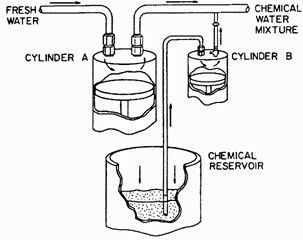
Another way of driving the injector using irrigation water is in Figure 5. In this case, a mechanism contains two pistons of different sizes and a series of valves. The pressure in the irrigation system drives the larger piston. A smaller piston injects a chemical into the irrigation line.
Credit: undefined
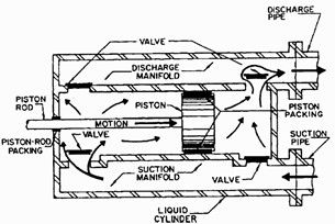
Piston and diaphragm pumps inject chemicals in concentrated pulses separated in time. Some pumps are equipped with double-acting pistons or diaphragms to minimize variations in the concentration of chemicals in the irrigation system. In these cases, the volume on both sides of the piston or the diaphragm is used for pumping chemicals (Figure 6). If the pipeline length between the injection port and the first application point is short, a blending tank should follow the injection for adequate water and fertilizer mixing.
Credit: undefined
Rotary Pumps
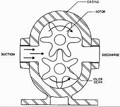
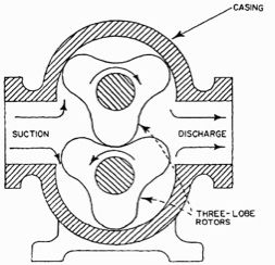
Rotary pumps transfer chemicals from suction to discharge through the action of rotating gears, lobes, or other similar mechanisms. Gear and lobe types of rotary pumps are often for chemical injection into irrigation systems. Gear and lobe pump operations are based on the partial vacuum created by the enmeshing of the rotating gears (Figure 7) or lobes (Figure 8). This vacuum causes the chemical to flow into the pump. Then, it is carried between the gears or lobes and the casing to the discharge side of the pump. Gear and lobe pumps produce approximately constant flow for a given rotor speed, and the injection rate does not change with the flow rate in the irrigation system. Flow sensors described above for reciprocating pumps can assure a constant injection rate (Bajpai, 2018).
Credit: undefined
Credit: undefined
Peristaltic Pumps
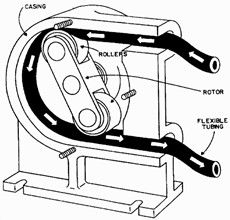
Peristaltic pumps are typically used in chemical laboratories and for the injection of chemicals into small irrigation systems. Their capacity is limited, and most of them produce a pressure of only 30 to 40 psi. A typical peristaltic pump is in Figure 9. A set of rollers press a flexible tube, creating an even flow. The pump is suitable for pumping corrosive chemicals since the pumped liquid is completely isolated from all moving parts of the pump.
Credit: undefined
Pressure Differential Methods
The idea of injection using pressure differential is quite simple. The chemical flows into the line if the pressure at the injection point is lower than at the chemical intake. Several injection techniques use the above principle and represent two distinctive groups – injection on the suction side of the irrigation pump and injection on the discharge side of the irrigation pump.
Suction Pipe Injection
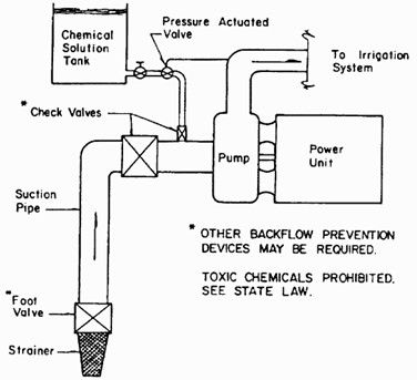
The suction pipe injection technique can be used in irrigation systems operating centrifugal pumps on the surface water source, such as a pond, lake, canal, or river. In Florida, this method is not permitted for irrigation systems using groundwater supply, and it is approved for fertilizer injection only (see IFAS Extension Bulletin 217).
The method described above requires only a minimum investment. The equipment necessary for this type of injection is a pipe or a hose, a few fittings, and an open container to hold the fertilizer solution (Figure 10). The rate of chemical flow depends on the suction produced by the irrigation pump, the length and size of the suction line, and the level of the chemical in the supply tank. This rate cannot be easily adjusted (Palgrave, 2019).
Credit: undefined
Discharge Line Injection
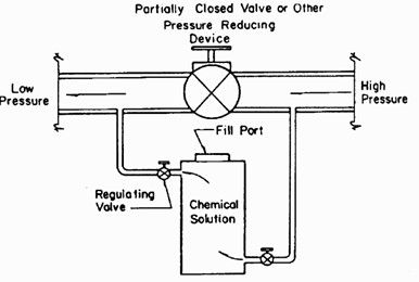
The differential pressure injection technique can also be used on the discharge side of the pump. This technique is usually done by redirecting part of the main flow through the chemical tank and providing a pressure drop in the irrigation line between the point where the water is taken and where the chemical enters the irrigation line. The pressure drop is accomplished using a line restriction, such as a valve, orifice, pressure regulator, or another device that would create a pressure drop. Valve use allows for pressure drop adjustment and, therefore, injection rate adjustment (Botermans, 2013).
Pressurized Mixing Tanks
A mixing tank injector operates at the discharge line on a pressure differential concept. The water is diverted from the main flow, mixed with fertilizer, and injected or drawn back into the mainstream (Figure 11). A measured amount of fertilizer required for one injection is placed in the cylinder. The flow back into the mainline is often controlled by a metering device installed on the inlet side of the injector. The concentration of the injection changes as the chemical becomes diluted as the water enters the tank during the injection. To operate, as described previously, there must be a pressure differential in the irrigation line between the inlet and the outlet of the injector.
Credit: undefined
Proportional Mixers
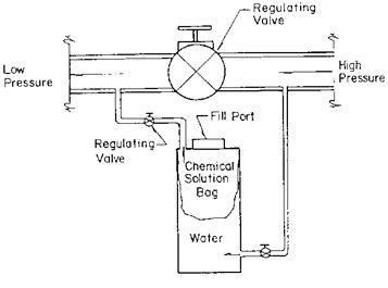
Proportional mixers are modified pressurized mixing tanks. They operate on the displacement principle. The chemical is placed in a collapsible bag, separating the chemical from the water (Figure 12). The amount of chemical forced into the proportioning valve is replaced with displacement water outside the chemical solution bag. As water enters the tank, it displaces chemicals and never returns into the system. As long as the pressure and the flow rate in the system do not vary significantly, the injection rate will remain constant.
Credit: undefined
Irrigation systems with expected flow fluctuations use proportioning control valves. If the injector is a true proportional mixer, the proportioning valve must respond to the flow changes, not pressure changes in the irrigation system.
Venturi Injector
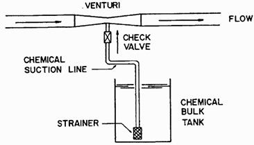
Chemicals can be injected into a pressurized pipe using the venturi principle. A venturi injector is a tapered constriction that operates on the principle that a pressure drop accompanies the change in velocity of the water as it passes through the constriction. The pressure drop through a venturi must be sufficient to create a negative pressure (vacuum) as measured relative to atmospheric pressure. Under these conditions, the fluid from the tank will flow into the injector (Figure 13) (Li, 2020). Most venturi injectors require at least a 20% differential pressure to initiate a vacuum. A full vacuum of 28 in of mercury is attained with a differential pressure of 5% or more.
Credit: undefined
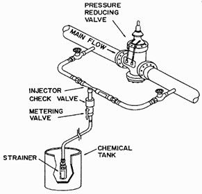
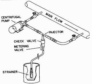
A small venturi can inject small chemical flow rates into a relatively large mainline by shunting a portion of the flow through the injector. To assure that the water will flow through the shunt, a pressure drop must occur in the mainline. For this reason, the injector is used around a point of restriction, such as a valve, orifice, pressure regulator, or another device that creates a differential pressure (Figure 14). A centrifugal pump, used to provide additional pressure in the shunt (Figure 15), can also be used.
Credit: undefined
Credit: undefined
A venturi injector does not require external power to operate. It does not have any moving parts, which increases its life and decreases the probability of failure. The injector is usually constructed of plastic and is resistant to most chemicals. It requires minimal operator attention and maintenance. Since the device is simple, its cost is low compared to other equipment with similar functions and capabilities. It is easy to adapt to most new or existing systems, providing sufficient pressure in the system exists to create the required pressure differential.
Venturi injectors come in various sizes and can be operated under different pressure conditions. Suction capacity (injection rate), head loss required, and working pressure range will depend on the model. It is critical to realize that the suction capacity depends on the liquid level in the supply tank. As the liquid level drops, the suction head increases, resulting in a decreased injection rate. To avoid this problem, some manufacturers provide an additional small tank on the side of the supply tank, where the float valve maintains the fluid level relatively constant. The fluid is injected from this tank (Li, 2020).
Combination Methods
Some injectors on the market employ a combination of the different principles of injection at the same time. The most common is a pressure differential combined with a venturi meter or some measuring device that operates on the venturi principle.
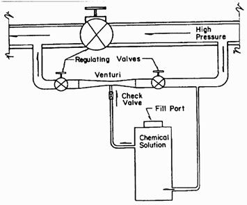
Direct use of pressure differential combined with a venturi can be found in some systems where the pressure drop required for a venturi may be difficult to provide due to design restrictions of the existing irrigation system. The combination of a venturi device with a pressurized chemical tank may be used in this case (Figure 16). The chemicals are placed in the tank. Since the water flowing through the tank is under pressure, a sealed airtight pressure supply tank, constructed to withstand the maximum operating pressure, is required. In this case, the injection rate will change gradually due to the change of chemical concentration in the tank as the water enters the tank during the injection.
Credit: undefined
Various metering valves used with mixing and proportioning tanks operate on pressure or flow changes in the irrigation system. There are many designs of these valves. Frequently, it is some application of the venturi meter or the orifice with changing diameter. The manufacturer should be contacted for descriptions and operation instructions for various metering and proportioning valves.
Backflow Prevention Law
Before injecting any chemicals into an irrigation system, it is necessary to check that the system is provided with the required backflow prevention system for a given type of chemical. The general rules for backflow prevention in Florida are in UF/IFAS Extension Bulletins 217 and 248. In addition, it is important to check local ordinances since they may be more restrictive.
Chemical injection on the suction side of a centrifugal pump is generally not permitted in Florida. The exception is a system that uses a surface water supply and only injecting fertilizers into the system. Florida Backflow Prevention Law requires that double protection of a check valve and a foot valve will be used upstream of the injection port in this case. Florida code 62-555 requires installation of an approved backflow connection device installed under supervision of the water supplier (FDEP, 2021).
According to Environmental Protection Agency (EPA), only piston and diaphragm injection pumps can be used for pesticides and other toxic chemicals. Other methods described in this publication can be used for fertilizer or cleaning agent injection, such as chlorine or acids.
Summary
This publication discusses different types of injectors. These injectors are classified into five groups depending on their principles of operation. Basic principles of operation, advantages, and disadvantages are presented.
References
Bajpai, P. (2018). Chapter 23 - Hydraulics. In Biermann's Handbook of pulp and Paper: Paper and board making (pp. 455–582).
Botermans, R., & Smith, P. (2013, October 30). Pumps. Advanced Piping Design.
Bloch, H. P., & Geitner, F. K. (1997). Chapter 3 - Reciprocating and Liquid Ring Vacuum Pumps. In Practical machinery management for process plants. essay, Gulf Pub. Co.
Chapter 62-555 f.a.c. CODED draft rule May 2021. Florida Department of Environmental Protection. (2021). https://floridadep.gov/water/source-drinking-water/documents/chapter-62-555%C2%A0fac-coded-draft-rule-may-2021
Ebrahimian, H., Keshavarz, M. R., & Playán, E. (2014). Surface fertigation: A review, gaps and needs. Spanish Journal of Agricultural Research, 12(3), 820. https://doi.org/10.5424/sjar/2014123-5393
Karassik, I. J., & McGuire, T. (2012). Centrifugal pumps. International Thomson Publishing.
Kowalski, J. (2001). Fans, pumps, and compressors. Academia.edu. https://www.academia.edu/18076037/Fans_Pumps_and_Compressors
Li, H., Li, H., Huang, X., Han, Q., Yuan, Y., & Qi, B. (2020). Numerical and experimental study on the internal flow of the venturi injector. Processes, 8(1), 64. https://doi.org/10.3390/pr8010064
Palgrave, R. (2019, November 27). Chapter 5 - Pipe system basics. Troubleshooting Centrifugal Pumps and their systems - 2nd Edition. https://www.elsevier.com/books/troubleshooting-centrifugal-pumps-and-their-systems/palgrave/978-0-08-102503-1
Purcell, J. E., & Silvaggio, J. A. (1997, January 1). A comparison of positive displacement and centrifugal pump applications. OAKTrust Home. https://oaktrust.library.tamu.edu/handle/1969.1/164131
Stewart, M. (2019). Pump fundamentals. Surface Production Operations, 7–59. https://doi.org/10.1016/b978-0-12-809895-0.00002-8
Table 1. Comparison of various chemical injection methods.