The term "valve" applies to a variety of devices for controlling the flow of liquid. Various valves allow for on-off control, modulation of the flow rate through the system, and prevention of back flow. They can also be used for pressure relief or as a safety device. In general, valves can vary from simple manual on-off devices to sophisticated control equipment which act as metering instruments and deliver predetermined amounts of water to the system.
On-Off Service Valves
For normal on-off control the best choices are gate, ball, and plug valves. The on-off service valves function by sliding or by turning a flat, cylindrical or spherical flow control element over an orifice in the valve body. Leakage past the flow control element is prevented by sealing or seating surfaces at the orifice. In the fully open position a passage through a gate, ball or plug valve is unrestricted resulting in a low pressure loss through the valve.
Gate Valves
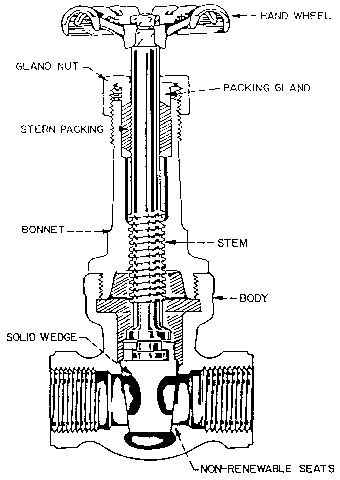
A gate valve is the most common type of on-off service valve (Figure 1). Its flow control element is a disk or wedge attached to the valve stem. There are various designs of these wedges with a solid wedge being the most common. A solid wedge has the advantage of positive contact with the wedge guides which reduces chatter when the valve is in a partially closed position. When in the fully open position, the wedge completely clears the flow path creating minimum loss through the valve.
Other types of wedges can be used, such as split wedge, double disk parallel wedge, or a combination of disks joined by a ball and socket which are self-aligning to each of the inclined resting faces (Figure 2).
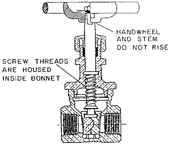
Gate valves can be also classified based on the stem movement. The stem is a shaft used to control the position of the wedge. Stems can be classified into three groups: two types of rising stem (outside or inside thread) and nonrising-stem. Figure 1 represents a rising-stem type of valve, where a nonrising-stem valve is shown in Figure 2.
With a rising-stem it is easier to determine how far the valve is open at a given time since the threaded portion of the stem is exposed. However, sufficient space must be provided to allow for the rise of the stem when the valve is in the fully open position.
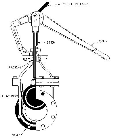
All valves described above are slow acting due to the turning required for changing the position of the control element. For a quick acting valve, the stem can be constructed in such a way that it slides up or down through the action of a mechanical lever (Figure 3).
Gate valves should not be used for throttling or controlling liquid streams. Most of the shut-off of this valve takes place when the valve is almost closed. As a result, the flow control profile is not linear and difficult to control. At the same time, the decrease of flow area in partially closed positions, significantly increases the liquid velocity. This can result in quick erosion of the wedge and destruction of the lower seating surface.
Plug Valves
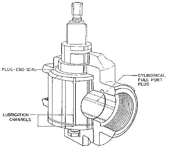
A plug valve is also intended as an on-off type of valve. The flow control element is a plug which is transversely pierced to allow liquid to flow when the pierced section is exposed by turning the plug 90° (Figure 4). Plug valves do not have linear flow characteristics when partially closed. As a result they are difficult to use for flow regulation. Some plug valves are provided with special plug ports and can be used for throttling. However, unless specified by the manufacturer, plug valves in general are not recommended for flow control operations. Similar to a gate valve, partial closing of a plug valve can cause a rapid wear of internal parts. The main advantage of a plug valve is that it is compact and simple to construct.
Ball Valves
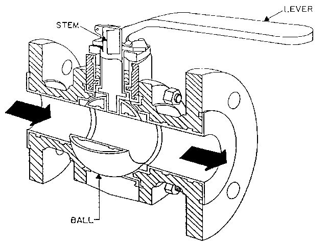
A ball valve is a modification of the plug valve with the plug replaced by a spherical flow control element (Figure 5). Like a plug valve this valve is very compact and operates on 90° turns. Ball valves are full-flow units and create minimum pressure loss through the valve when fully open. Like gate and plug valves, due to nonlinear flow characteristics, ball valves are not recommended for flow regulation unless specifically designed for throttling.
Throttling and Control Valves
Throttling and control valves are used when the flow rate through the pipe must be controlled at some rate below the maximum flow. An ideal throttling or control valve exhibits a linear flow response to partial closing. This is accomplished by the special design of the flow path through the valve. Generally, manually operated valves are called throttling valves, where automatically activated ones are called control valves.
Throttling Valves
The following valves are recommended for throttling since their flow control characteristic curves are approximately linear: globe, angle, needle, pinch, diaphragm, and butterfly.
Globe Valves
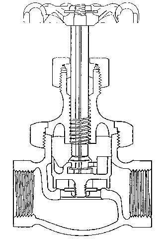
Globe valves are widely used for flow control. A tapered plug or disk, which closes onto a seating surface, acts as a flow control element in this type of valve (Figure 6). The position of the disk and the seating surface results in the necessary linear flow response. The globe valve is always controlled by a rising-stem so a sufficient space must be provided for opening the valve. The design of the valve does not provide an unrestricted flow passage when the valve is fully open since even at this position the liquid must make two 90° turns when passing through the valve. Because of that, pressure drop in the globe valve is much more significant than in a gate valve when fully open. A high-pressure drop is the main disadvantage with this type of valve. Globe valves are sometimes used for on-off service but the loss of pressure through the valve should be taken under consideration in the design of the plumbing system (Table 1).
Angle Valves and "Y" Valves
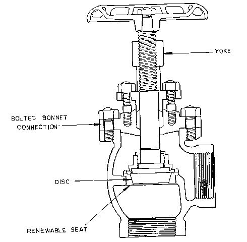
Angle valves (Figure 7) and "Y" valves (Figure 8) are designed with the objective of decreasing pressure losses in the valve while maintaining linear flow characteristics. In the angle valve this is accomplished by fewer number of bends within the valve as compared to a globe valve. The liquid takes only one 90° turn passing through an angle valve.
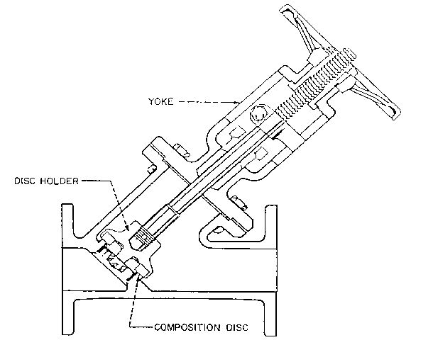
A “Y” valve forces liquid into two turns similar to a globe valve, however, the severity of the bends is decreased, and the liquid makes two 45° turns. This gives a relatively unrestricted flow path which is nearly as free as in a gate valve. Due to relatively low-pressure loss “Y” valves as well as angle valves are sometimes used for on-off service (Table 2).
Needle Valves
A needle valve is usually intended for small flows and their use with irrigation systems is generally limited to chemical injection. The flow control element is a long-taper or needle-like plug that fits into the valve seat and allows for very close control of the flow through the valve. Applications of this valve are usually limited to throttling (Table 2).
Pinch Valves
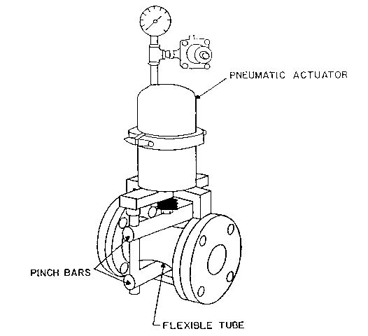
Another valve which may have use in some chemical injection applications is a pinch valve. This valve consists of a flexible tube and a set of pinch bars, one movable and the other stationary. It has nearly linear flow response and can be used for throttling. In addition, it has an advantage of simple design. Also, the only component in contact with the liquid is the flexible tube which eliminates corrosion problems (Figure 9).
Diaphragm Valves
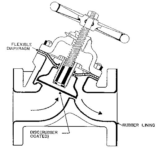
The main advantage of the diaphragm valve is the separation of the liquid from the stem and stem collar by a flexible diaphragm. To close the valve the diaphragm is forced against a partition or weir by the compression head (Figure 10). This valve has an additional advantage of low-pressure losses when fully open. The stem mechanism in diaphragm valves are similar to gate valves and can be rising, nonrising or sliding.
Butterfly Valves
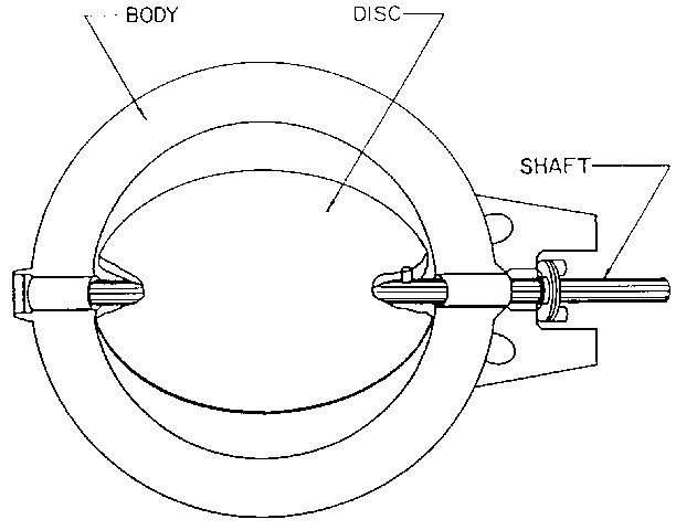
The flow control element in a butterfly valve is a disk pivoted on either a horizontal or a vertical axis within the valve body (Figure 11). This disk is placed in the parallel position to the flowing liquid when the valve is fully open, resulting in small friction losses. Butterfly valves are simple and compact and have good throttling characteristics. The flow response is approximately linear to the closing of the flow control element in these valves.
Control Valves
A combination of a valve and an actuator is usually referred to as a control valve. The system which provides automatic control of flow consists of a valve, a valve actuator, and a sensor device.
Two types of controllers and actuators commonly used in irrigation are electric and hydraulic. Globe and angle valves are commonly adapted for automatic control due to the tight shutoff of these valves. Control valves allow for remote operation of irrigation systems by turning the system on and off from a certain distance.
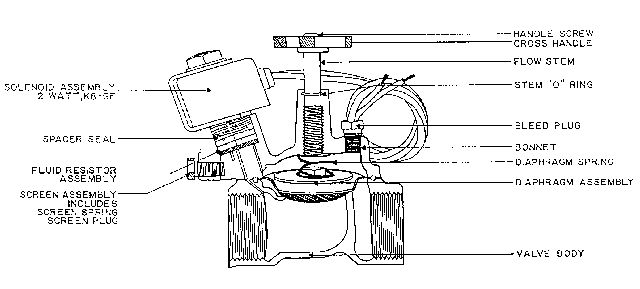
A piston or a flexible diaphragm is the basic flow control element used in these valves. The diaphragm operates by pressure differentials within the valve controlled by an electric (solenoid), as shown in Figure 12, or hydraulic actuator (Figure 13). Power to the actuator is transmitted as electrical current through wires or hydraulic pressure through small tubing.
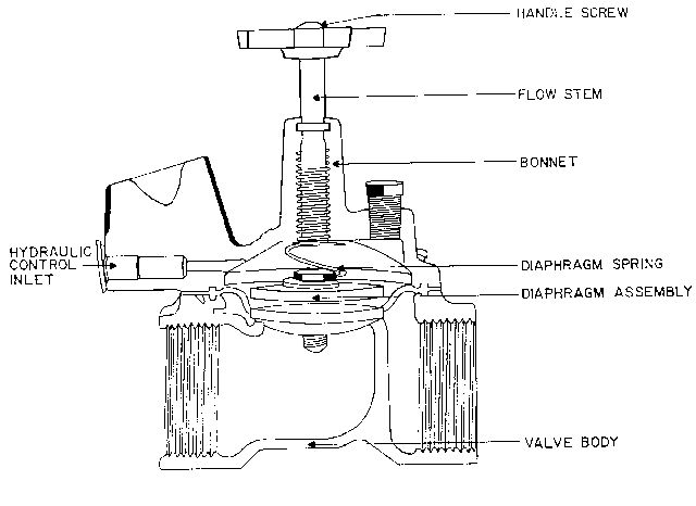
In addition to the type of power transmitted (hydraulic or electric) control valves can be classified by the position which the valve assumes when the power is off. Some valves are normally open when the power source is off, others are normally closed.
Electric Control Valves
Valves which use electric actuators (solenoids) are called electric control valves. Generally, the actual power transfer to the control element is hydraulic pressure activated by the electrical power delivered to the actuator. The flow controls element can be in the form of a plug, disk, piston or other similar device allowing for closing or opening of the flow path in the control valve. In some cases, the actuator piston can be a flow control element at the same time.
The solenoid valve, which is commonly used in irrigation systems relies on an electromagnetic force to move the disk directly (Figure 12) or to initiate the piloting action that allows line fluid to open the valve. Electric control valves can also be manually closed or manually opened.
Hydraulic Control Valves
The construction of hydraulic control valves is very similar to the construction of electrical control valve (Figure 13). The only difference is that power is transmitted by a change of pressure above the actuator (diaphragm or piston). This change of pressure is transmitted through the hydraulic control tubing or in some cases by diverting a portion of water flowing through the valve.
Most of the hydraulic control valves are normally open and power has to be transmitted to close these valves.
Check Valves
Check valves are valves that prevent flow in one direction. The control element maybe in the form of ball, disk lift, tilting disk, flapper or a swinging disk, and is lifted by the pressure of liquid flowing in the normal direction. It returns to the closed position due to gravity or gravity combined with spring action when the flow stops. The pressure caused by backflow or the weight of a water column in the line increases the force which presses the control element against the seat, further preventing a flow in the reverse direction.
Ball Check Valves
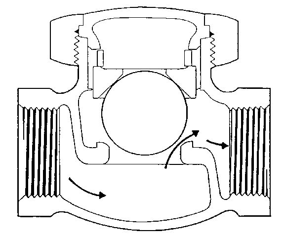
In this type of valve, a control element is a freely moving ball which fits into a seat and creates a seal (Figure 14). Because the ball remains in the liquid flow path, friction loss in those valves is relatively high.
Disk Lift and Piston Lift Check Valves
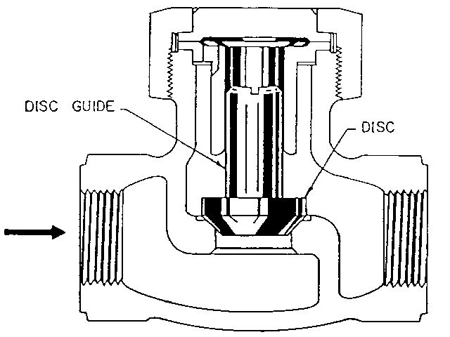
Disk lift and piston lift check valves are globe-type valves. The flow control element is a disk or piston which travels along a vertical axis (Figure 15). The alignment with the valve seat is provided by the plug or disk guides. Pressure drops in these valves are less than in regular globe valves.
Flapper or Swing Check Valves
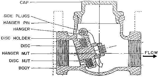
The flow control element in this type of valve is a flapper or swing disk which is pivoted at the point above the main flow path (Figure 16). When liquid flows in the desired direction a disk or flap swings away. Reversed flow quickly brings the disk back to the closed position. For a better contact, a disk can be equipped with a spring which requires some pressure buildup before it opens and helps bring the disk back to the closed position.
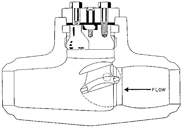
A tilting disk check valve (Figure 17) has a modification of a standard swing check valve which provides very rapid closing due to the position of the disk. The advantage of this valve is that it doesn't chatter or flutter like swing and ball check valves.
Diaphragm Check Valves
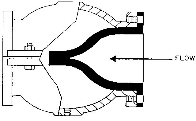
The check valve presented in Figure 18 consists of a flexible sleeve that is flattened on one end. This sleeve opens on forward flow but closes against reverse flow. The sleeve is usually made with material similar to an automobile tire. This valve is particularly suitable for fluids containing solids since inside of the sleeve is soft and capable of passing suspended solids.
Foot Valve
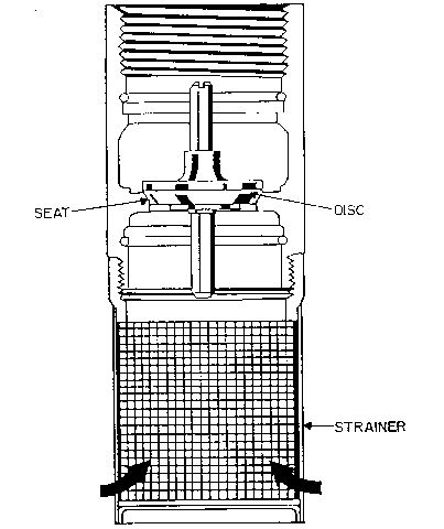
Foot valves are most often used to maintain a pump's prime. They are installed at the end of the suction pipe in order to prevent water from leaving a suction pipe and the pump when pump is not in operation (Figure 19).
Special Service Valves
A few special service valves which are sometimes used in irrigation systems will be discussed here. This includes pressure relief valves and pressure reducing valves.
Pressure Relief Valves
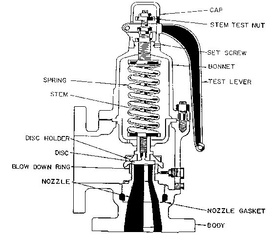
Pressure relief valves are used in the system to protect against excessive pressure. They are designed to open slowly and discharge small amounts of fluid to relieve excess pressure in the system. They are normally held in the closed position by means of a spring-loaded disc. This spring can be adjusted to provide a predetermined pressure limit. Excess pressure levels would open the valve and allow some fluid to be released. Set pressure is usually altered by means of a screw in the top of the bonnet which adjusts the spring compression. A pressure relief valve is presented on Figure 20.
Pressure Reducing Valve
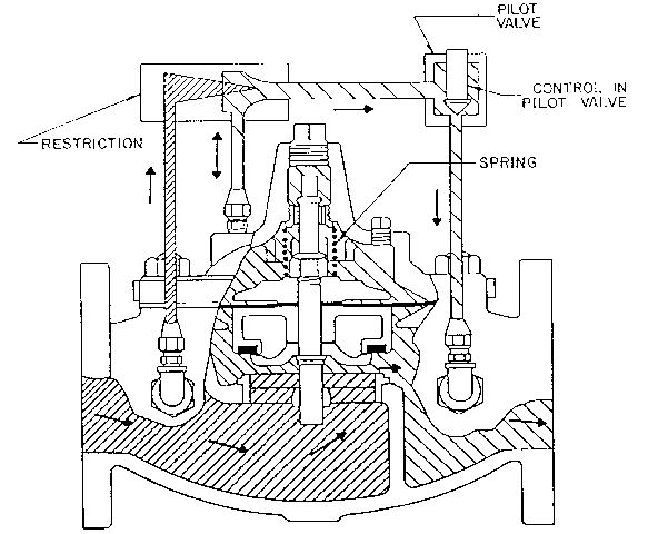
Pressure-reducing valves are used in irrigation systems where a predetermined lower pressure is necessary for the proper function of certain components such as emitters in micro-irrigation systems. They can be also used in systems with variable pressure to maintain a lower constant pressure downstream of the valve. Pressure reducing valves usually consist of two valves built much like the diaphragm and spring-loaded relief valve.
The valve is throttled by the action of an adjusted spring on the top of the diaphragm and the pressure of the fluid underside of the diaphragm. The water from the reduced pressure side of the valve is diverted into the chamber above the diaphragm to compensate for the compression of the spring as the upstream pressure changes. This action throttles the controlling valve and allows the pressure to remain at the set level. The construction of the pressure regulated valve is presented in Figure 21.
Miscellaneous Valves
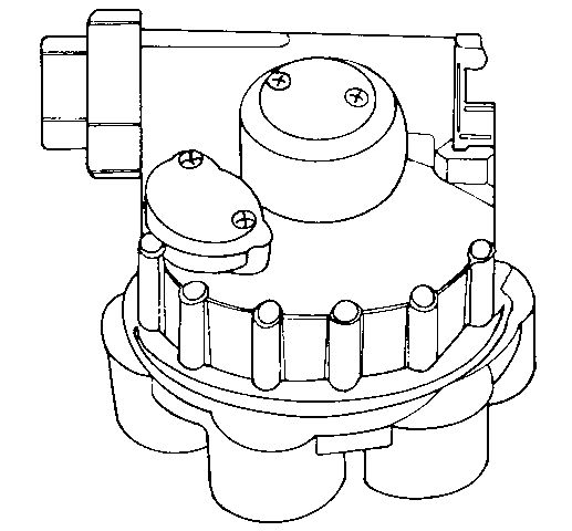
Two types of valves frequently used in lawn irrigation systems discussed here are automatic distributing valves and battery-operated programmable valves.
The automatic distributing valve permits the irrigation system to be switched from one zone to another by turning the water supply on and off in sequence. A hard rubber disc with an opening is located inside the valve. This disc is ro- tated to a new outlet for each pressure cycle (pump off, then on). By using different cams, which are easily exchangeable, it is possible to automatically switch from one to six zones. The use of this valve eliminates the necessity of using many control valves for each zone. A six-outlet automatic distributing valve is presented in Figure 22.
A battery operated programmable valve is presented in Figure 23. This programmable valve includes two 9-volt batteries. A controller which is mounted on the valve allows for programming of irrigation events. The controller allows setting frequency of irrigation, the length of watering, and the time of day when irrigation should begin.
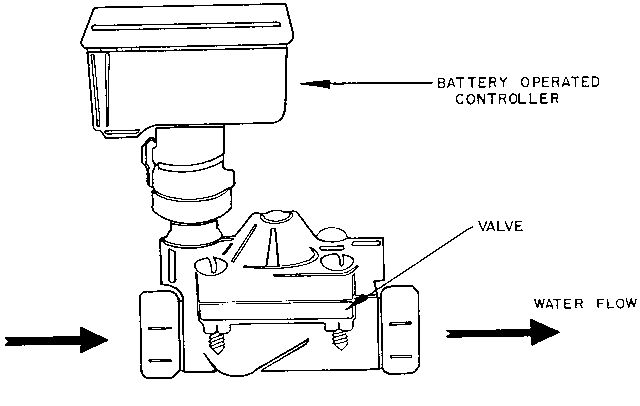
Normally every zone requires one programmable valve. However, it is possible to water a few zones by combining a programmable valve with an automatic distributing valve.
Valve Sizing
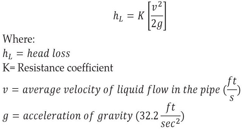
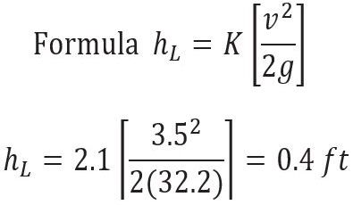
When a valve is a part of irrigation pipeline, the overall resistance to flow increases. Pressure drop through a valve can be calculated from Equation 1: The resistance coefficient K, for a given type of valve tends to vary with size as does the friction factor for straight pipe and is determined experimentally. Some values of the resistance coefficient for different valves are given in Table 1.
Example 1: Determine the pressure loss through a 4-inch flanged angle valve knowing that velocity of the water in the irrigation system is 3.5 ft/sec.
From Table 1, K = 2.1 for 4-inch flanged angle valve. Using equation 1 for the calculation: This can be easily converted to pounds per square inch of pressure, psi (1 psi = 2.31 ft) or 0.4 ft = 0.17 psi.
Credit: undefined
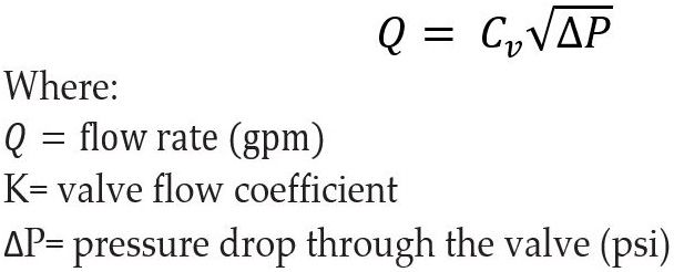
Some manufacturers express the valve capacity in terms of a flow coefficient, Cv. This parameter is frequently used for valve sizing especially for control valves. It is the number of gallons per minute of 60°F water that will flow through the valve at a 1 lb/in2 pressure drop across the valve. The maximum Cv, which is measured with the valve fully open is accepted as a measure of the valve size. For water at 60°F it is expressed by Equation 2: If the Cv is known for a given valve, the amount of flow can be determined for a given pressure drop. Conversely, the pressure drop can be found for a specified flow. If the amount of flow and the pressure drop are known, Cv can be calculated, and a matching valve can be found. An example of flow coefficients is presented in Table 3.
Example 2: For a valve with flow characteristics described in Table 3, what pressure loss will occur in 3-inch valve with a flow of 250 gpm?
From Table 3, Cv = 96 for a 3 inch valve.
Using Equation 2 to perform the calculation: Some manufacturers present the relationship between size, flow and pressure loss for a given valve in a table. Given flow rate and desired pressure drop, the required size of valve can be directly read from such a table.
Credit: undefined
Credit: undefined

Credit: undefined
Summary
Different types of valves, their construction and function were discussed in this publication. Recommendations for particular use of each type of valve were given and justified. In addition a method of valve sizing was presented.
References
Lyons, J. L. and C. L. Askland. 1975. Lyons' Encyclopedia of Valves. Van nostrand Reinhold Company, New York.
Schweitzer, P. A. 1972. Handbook of Valves. Industrial Press Inc., 200 Madison Ave., New York, NY 10016.
Karassik, I. J., W. C. Krutzsch, W. H. Fraser and J. P. Messina. 1976. Pump Handbook. McGraw-Hill, Inc., New York.
Holland, F. A. and F. S. Chapman. 1966. Pumping of Liquids. Reinhold Publishing Corp., New York.