Introduction
Infiltration rates can be measured in a variety of ways. Some of the most common methods involve ponding water over a given soil area for a period of time. Single and double ring infiltrometers are commonly used to determine infiltration rate. Double ring infiltrometers minimize the error arising from lateral flow of water compared to the single ring method, thereby making them more reliable (Gregory et al. 2005). Double ring infiltrometers are commonly fitted with a 15-cm diameter inner ring and 30-cm diameter outer ring. Both single and double ring infiltrometer methods commonly begin with a known volume of water at Time 0 and calculate the infiltrated volume of water at various time intervals.
Infiltration is measured using a falling or constant head within the rings. If the water level in the inner ring is measured, it is called a falling head test. If the level of water remains constant in the inner ring and the amount required to maintain that level is measured, it is called a constant head test. If the head pressure within the rings is not constant (falling head test), the variable head pressure of the water column introduces error to the measurement. While the falling head test is easier to employ, it is less accurate. Research has shown that infiltration rates for different types of soil differ under these two methods (Wuet al. 1997). Infiltration rates have been found to be underestimated on coarse textured soils using the falling head test. However, not much difference was observed on fine textured soils using both falling and constant head tests (Wuet al. 1997). Therefore, on coarse soils, an infiltrometer using a Mariotte siphon enables better measurement of infiltration by employing a constant head test. Constant head tests are suitable to determine infiltration on sandy soils (ASTM D3385-18 2018), such as those commonly found in Florida.
A Mariotte siphon is based on the principle of a Mariotte bottle, which discharges liquid at constant pressure. Moreover, the difference in height between the bottom of the air tube and exit hole of the siphon maintains a constant head in the inner infiltrometer ring (Bouwer et al. 1986) (Figure 1). The use of a Mariotte siphon with a double ring infiltrometer allows a single person to maintain a constant head accurately compared to manually maintaining a constant head (Gregoryet al. 2005). However, a commercially purchased Mariotte siphon double ring infiltrometer typically costs $2,500 for a single unit. The high cost is a limiting factor which prompts the use of less accurate infiltrometer methodology (Bouwer 1986).
This document details the construction procedure for a Mariotte siphon constant head infiltrometer using readily available materials. This information is meant for researchers, Extension agents, consultants, and agricultural and engineering professionals interested in gathering accurate data from infiltration rate measurements or other applications for automating the refill of small reservoirs over time.
Mariotte Siphon Schematic Design
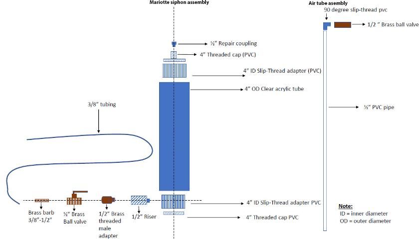
Credit: Eban Bean, UF/IFAS
Note
- PVC slip connections should be glued to be airtight.
- Teflon tape should be used at PVC and brass threaded connections to ensure airtight seals.
- Shapes with faded lines are threaded.
- The top valve is used to seal off the entry of air into the system through the inner tube and create a vacuum at the top of the siphon, which will slow the flow of water out of the siphon.
- Repair couplings act as a compression connection that allows the inner PVC pipe position to be adjusted.
Parts List with Cost and Source
Table 1. Cost of building a Mariotte siphon and a set of double rings.
Table 2. Material supplier source list for parts.
Table 3. List of tools needed for construction.
Summary for Construction
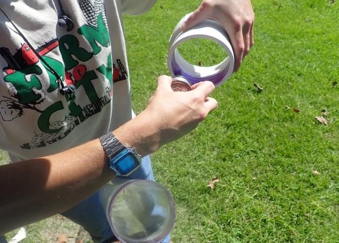
- Obtain the parts prior to construction (Figure 2). Parts and prices are shown in Table 1. Acrylic tubes may need to be ordered (Figure 3). Other materials are readily available at general home improvement and hardware stores.
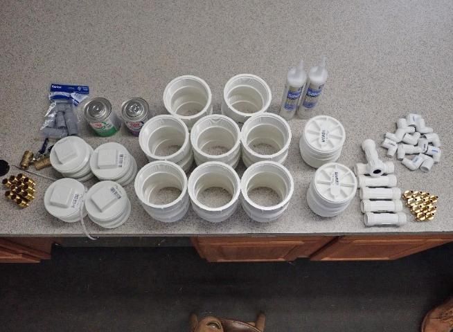
Credit: Cropping System Lab, UF/IFAS
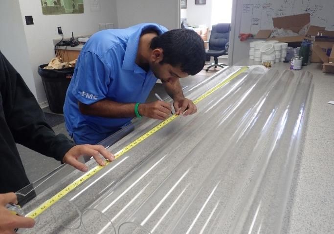
Credit: Cropping System Lab, UF/IFAS
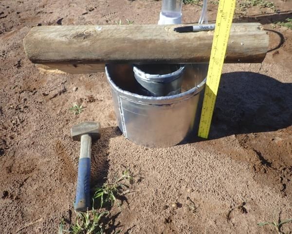
2. A set of double rings may need to be fabricated at a local machine shop. The rings shown were manufactured from aluminum sheet metal measuring 5.9 inches (15 cm) and 11.8 inches (30 cm) in diameter from a local machine shop (Figure 4). The thickness of the sheet metal at the top was 4/16 inch (0.64 cm) while the thickness for the bottom portion was 2/16 inch (0.31 cm). The bottom portion has an outside bevel to facilitate insertion into the soil.
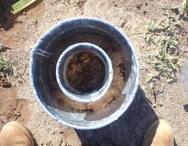
Credit: Cropping System Lab, UF/IFAS
Credit: Cropping System Lab, UF/IFAS
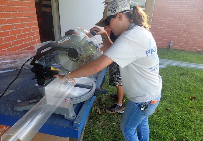
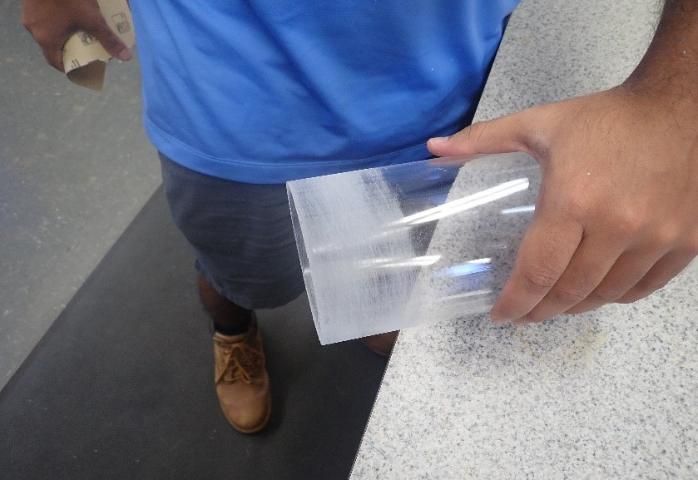
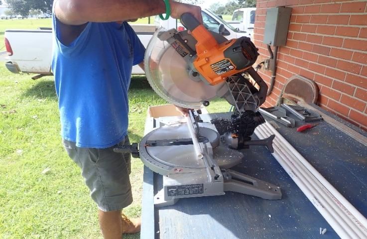
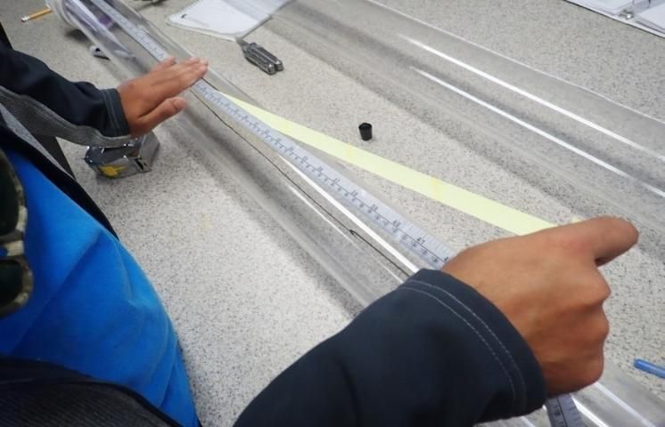
3. The acrylic tube is cut to a length of 4 ft (Figure 6), giving a capacity of 3.3 gallons (12.5 liters) of water for the infiltration test. The length of acrylic tube will determine the volume of the water available for use during the test.
Credit: Cropping System Lab, UF/IFAS
Credit: Cropping System Lab, UF/IFAS
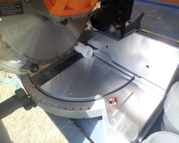
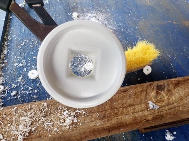
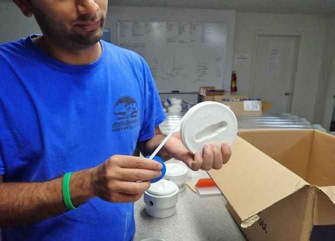
4. There are two portions that will fit onto the acrylic tube, a top and a bottom. Begin construction of the top portion first. The top portion includes a 1/2-inch repair coupling cut in half (Figure 8), which will be attached to a 4-inch threaded cap drilled with a hole saw (1-inch diameter) (Figure 9).
Credit: Cropping System Lab, UF/IFAS
Credit: Cropping System Lab, UF/IFAS
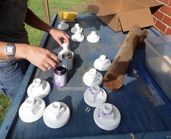
5. Primer is applied to facilitate gluing with PVC cement between the cut repair coupling and threaded cap (Figure 10). The assembly will later be screwed over the top of a PVC slip thread adapter. These PVC slip thread adapters are used to make the top and bottom ends of the siphon. The one without a hole on the side is used for the top end while the drilled adapter with a hole on the side for the outlet portion is used for the bottom (Figure 12). The air tube will go through the hollow repair coupling into the siphon.
Credit: Cropping System Lab, UF/IFAS
Credit: Cropping System Lab, UF/IFAS
Credit: Cropping System Lab, UF/IFAS
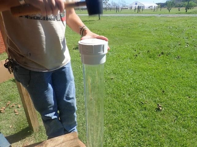
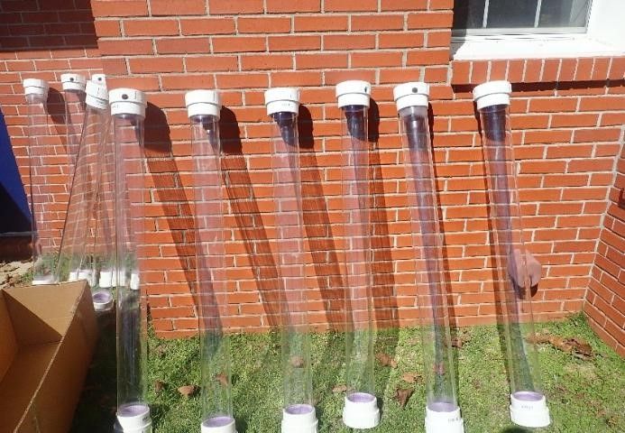
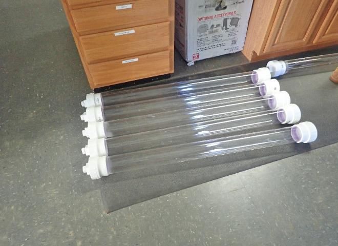
6. Primer and glue are applied to the surfaces of slip thread adapters. The adapters are fitted to the acrylic tube at both the top and bottom ends gently by hammering with a rubber mallet (Figure 14).
Credit: Cropping System Lab, UF/IFAS
Credit: Cropping System Lab, UF/IFAS
Credit: Cropping System Lab, UF/IFAS
Credit: Cropping System Lab, UF/IFAS
Credit: Cropping System Lab, UF/IFAS
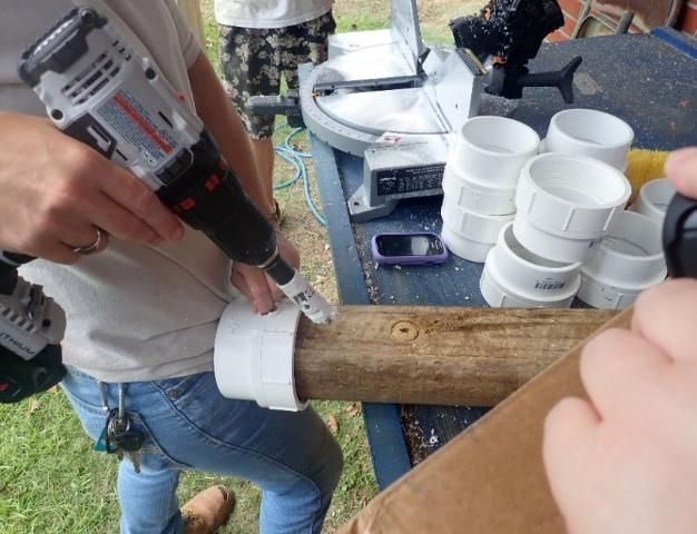
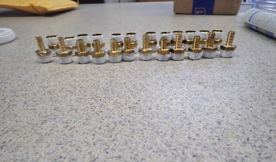
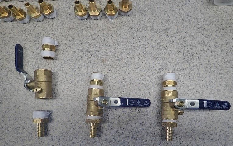
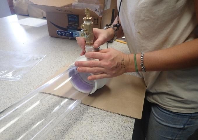
7. After the bottom slip thread adapter is glued into the acrylic tube, an outlet port is assembled. Drilling a hole into the bottom adapter enables the formation of an outlet port, which consists of the riser, male adapter, ball valve, and brass barb (Figure 18 and Figure 19). For the outlet port, Teflon tape is added to a brass male adapter, brass ball valve, and brass barb, which are assembled first and then connected to a riser (Figure 20). The riser is then glued to the bottom slip thread adapter, which was drilled out using a hole saw with a 1-inch diameter. The outlet port is then connected to the acrylic tubing for water discharge.
Credit: Cropping System Lab, UF/IFAS
Credit: Cropping System Lab, UF/IFAS
Credit: Cropping System Lab, UF/IFAS
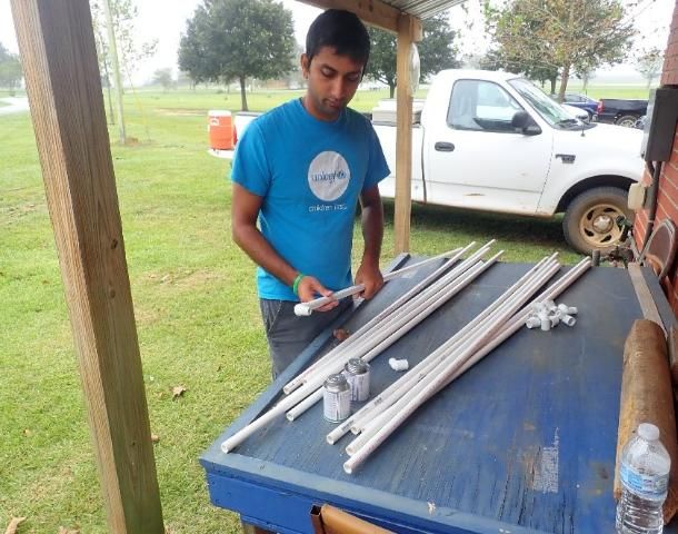
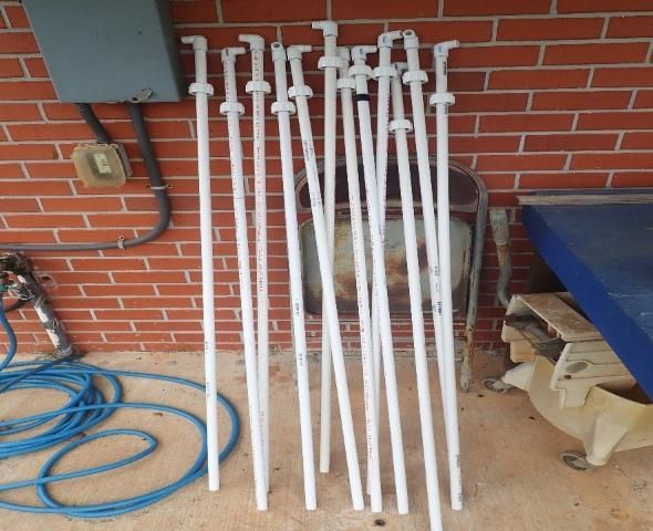
8. An air tube is cut from a Schedule 40, ½-inch PVC pipe and is connected to an elbow (Figure 22) and a ½-inch brass ball valve at the top. The brass ball valve regulates the pressure of the water column within the siphon. During measurement, this valve will be sealed to create a vacuum at the top of the siphon.
Credit: Cropping System Lab, UF/IFAS
Credit: Cropping System Lab, UF/IFAS
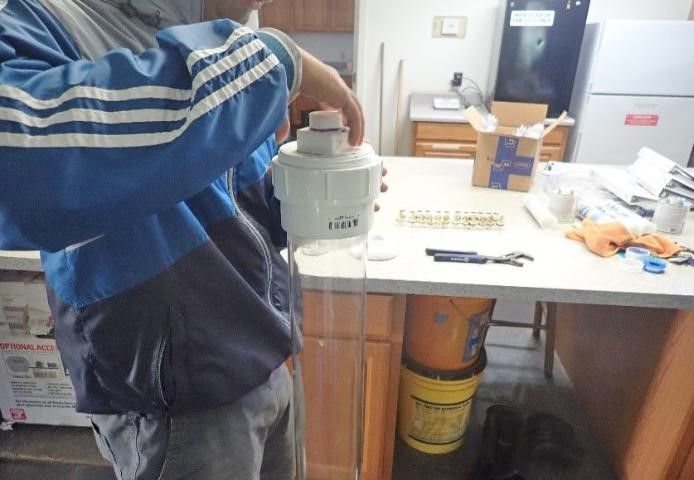
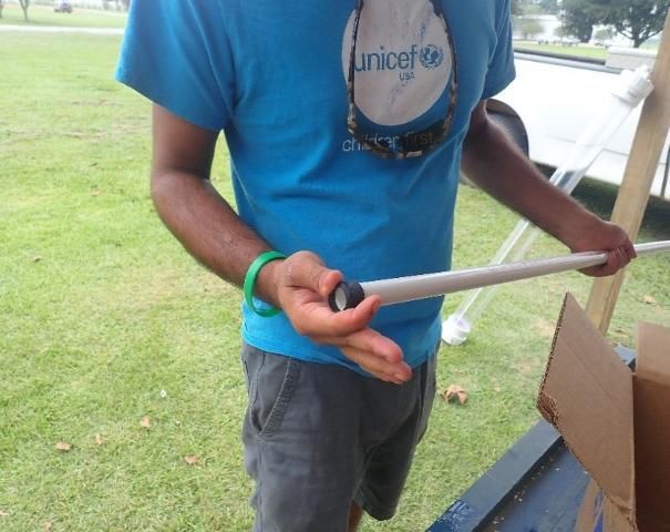
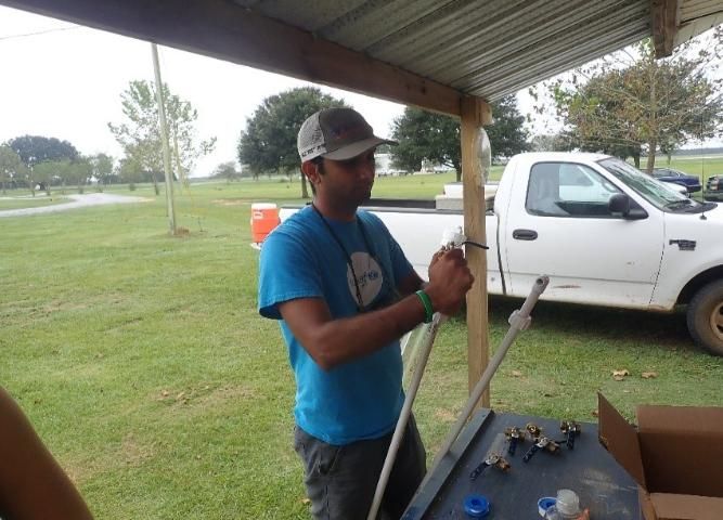
9. The cap of the repair coupling is inserted from the bottom of the tube. A rubber stopper or gasket is applied outside the air tube by inserting it over the ½-inch air tube. The rubber gasket is used to create an airtight seal at the top (Figure 23). A lubricant can be used to facilitate insertion of the rubber gasket.
Credit: Cropping System Lab, UF/IFAS
Credit: Cropping System Lab, UF/IFAS
Credit: Cropping System Lab, UF/IFAS
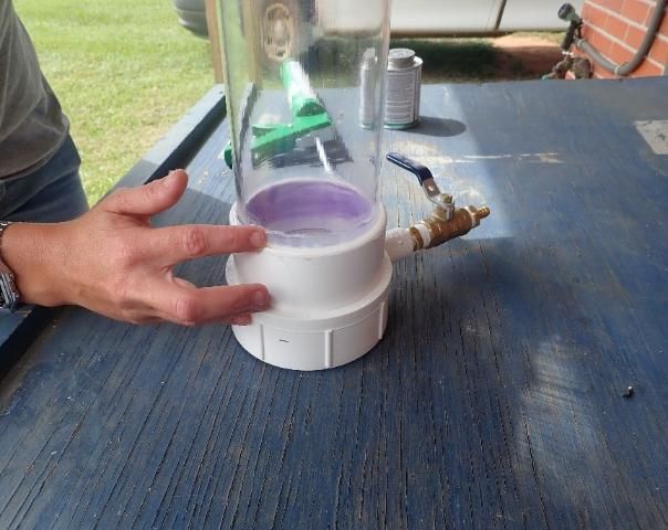
10. Silicone is applied with a caulking gun at the interface between the slip thread adapters and acrylic tube to prevent air leakage.
Credit: Cropping System Lab, UF/IFAS
Credit: Cropping System Lab, UF/IFAS
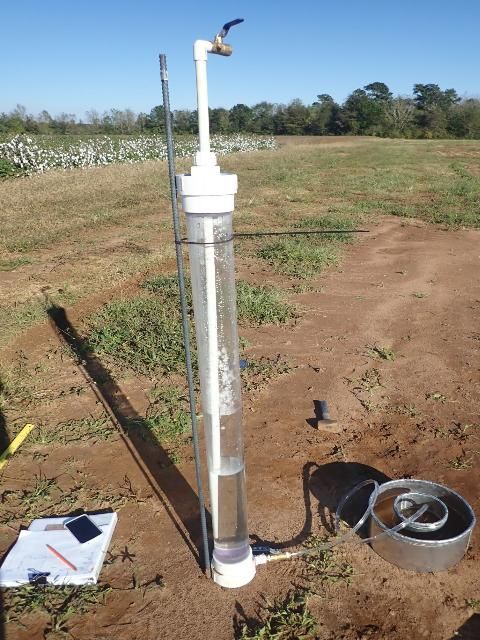
11. Siphon stands and zip ties are needed to keep the siphon in an upright position for ease of use and accurate reading. Rebar was used as a siphon stand, as it is cheap and easy to find (Figure 28). Note that the height of the bottom of the air tube will determine the water level in the inner ring.
Credit: Cropping System Lab, UF/IFAS
References
ASTM D3385-018. 2018. "Standard test method for infiltration rate of soils in field using double-ring infiltrometer." In Annual Book of ASTM Standards 04.08. West Conshohocken, PA: Amer. Soc. Testing Materials.
Bouwer, H. 1986. "Intake rate: Cylinder infiltrometer." Methods of Soil Analysis: Part 1—Physical and Mineralogical Methods: 825–844.
Gregory, J. H., M. D. Dukes, G. L. Miller, and P. H. Jones. 2005. "Analysis of double-ring infiltration techniques and development of a simple automatic water delivery system." Applied Turfgrass Science 2.
Wu, L., L. Pan, M. Roberson, and P. Shouse. 1997. "Numerical evaluation of ring-infiltrometers under various soil conditions." Soil Science 162: 771–777.